Erbium-Doped Fiber Amplifier & CW Laser
The goal of this project is to construct a high power fiber laser using double-clad fiber co-doped with erbium and ytterbium. Then to optimize the fiber laser, altering the length of the gain medium and the output coupling ratio to maximize output power.
Contents
Background
Optical fiber comes in two common types: single-mode and multimode, each with their own advantages and drawbacks. Single-mode fiber allows for higher beam quality with low propagation loss, but requires single-mode pump sources, which tend to be lower power and more expensive. Multimode fiber allows the use of higher power and less expensive multimode pump sources, but sacrifice beam quality and propagation loss in the process.
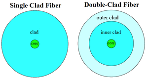
Double-clad fiber, however, offers the best of both fibers. Like its name suggest, double-clad fiber has two claddings, along with single-mode core. Double-clad fiber offers high beam quality with low propagation loss of the signal in the core, but supports higher power and less expensive multimode pumping of the inner cladding.
Fiber Laser Construction
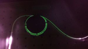
Our double-clad fiber ring laser, like all ring lasers, uses a positive feedback loop into a gain medium to achieve lasing. A 10 W 975 nm multimode laser diode is coupled into the inner cladding of the active fiber us a multimode pump coupler. The active fiber is co-doped with erbium and ytterbium. The erbium absorbs the pump light and emits 1550 nm light through the core, while the ytterbium only serves to increase the efficiency of the energy transfer. The signal light propagates through the core and into a coupler, where the majority of the light is sent through the feedback loop. An optical isolator in the feedback loop ensures light only propagates in one direction to reduce any possible loss. The feedback light is then sent into another end of the multimode pump coupler, where it is coupled into the core of the erbium-ytterbium doped fiber (EYDF) where it causes stimulated emission. The remaining portion of the signal light that is not returned as feedback exits the system as the output of the laser.
Controlling the Pump Laser
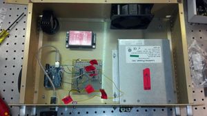
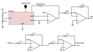
To power our pump laser, we are using a laser diode driver which drives 0-15 A based on a supplied 0-10 V signal. To control the signal, we created a graphical user interface using Python, with the modules Tkinter and PySerial, as well as an Arduino Duemilanove. The GUI allows us to set a 0-8 V signal (so as not to surpass the 12 A current limit of the diode laser) with 8-bit resolution using a digital-to-analog converter. All of these components were then built into a box to allow for simple operation of the laser diode.
Initial Results
After constructing the fiber laser, using an 80/20 output coupler and 1.5 m of active fiber, we were able to measure the output of the laser in response to the pump laser power.
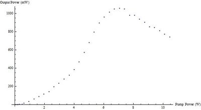
We discovered the laser had an output power of 140 mW with the pump laser at 10 W. But when the pump laser is at 7.1 W, the laser has an output power of 190 mW. We expect we are saturating the erbium-ytterbium co-doped fiber, but that would result in a gain curve which plateaus, not decreases. Investigating other high power lasers, we found a common loss mechanism is Stimulated Brillouin Scattering (SBS). SBS is a nonlinear loss mechanism that increases with pump power and temperature. This means that once we hit max gain on our EYDF, the increased effects of SBS force our laser's output power to decrease. To test this, we switched out the 80/20 2x1 output coupler with a 90/10 2x2 output coupler, which has an additional output for back-reflected light. If there was a significant amount of Stimulated Brillouin Scattering, the amount of light being back-reflected would match the drop in power. However, measuring the light out of the back-reflected endwe only detected 1.5 mW out of the 10% back-reflection end. Meaning there is only 15 mW of total back-reflection, and the loss cannot be due to SBS.
Now using the 90/10 output coupler, we also implemented a mode scrambler to increase the amount of pump light crossing the core in the active fiber. While the gain curve still has a similar shape, with the peak output power occurring near 7.1 W of pump power, the maximum output power improved drastically to over 1 W.
In an attempt to further increase the output power of the laser, we increased the size of the active fiber to 3 m. Our initial results were promising, measuring near 1.25 W of output power, however before we could characterize the output, the 10 W pump laser burned out.
Low Power Experimental Setup
After the 10 W pump laser burned out, we set up two 1 W diode lasers to pump our system. We set up one of the laser diodes on its own temperature controller and diode driver. For the other laser diode, we re-coded the Python GUI so it would only drive the 1.7 A needed to run the 1 W laser diode. The multimode pump coupler has two input ports, which we connected both pump lasers to, as can be seen below. We may investigate the effects of backwards pumping in the future.
The maximum output power measured was 297 mW at 2 W of pump power. When pumping near threshold, we noticed through the IR viewer that the second fusion splice pulses(the splice connecting the active fiber the dump WDM). Analyzing the output, we measured that the output also pulses with a frequency of 44 kHz. Although we have not yet been able to measure the amplitude of the pulsing, we have determined that our laser is self-pulsing. Self-pulsing is commonly caused by either low pump power or a long cavity length. When the pump is not able to maintain a complete population inversion, then the gain medium acts like a saturable absorber. When the cavity length is long, the light pulse will have more time until it is fed back into the gain medium, allowing the pump time to start saturating the gain medium again. Our laser has the right setup for self-pulsing, as the cavity is nearly 12.5 m long. However, once we pump the laser with more than 600 mW, the pulsing is suppressed. While an interesting result, self-pulsing should not be a problem in the future, as our setup can supply more than enough power to suppress the pulsing.
Future Work
The ultimate goal for the project is to build a high power, single-mode, tunable continuous wave laser in the 1550 nm range. To tune the laser, we plan on adding a Braggs grating into the ring cavity of the laser, to only allow the cavity to lase at a set frequency. While single-mode fiber only allows one transverse mode, we will have to add other components to eliminate all but one longitudinal mode. To achieve this, we plan to incorporate a fiber coupled Fabry-Perot cavity into the ring cavity, which will work with the Braggs grating to eliminate all but a single longitudinal mode. As well, we plan on increasing the pump power, but that depends on when we receive new diode lasers.
Constructing a High Power Single-Mode Fiber Laser (Honors College Thesis)
