Optics Obstacle Course
Permanent Materials (located on optical breadboard or in storage cabinet):

- Optics cleaning materials
- Helium Neon laser
- 4 mirrors
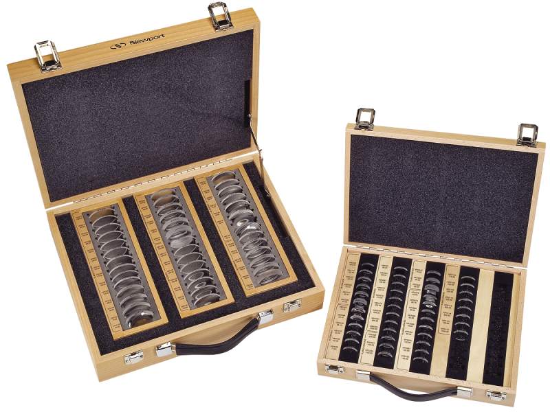
- Telescope lens pair (Newport KPX.097 and KPX.085)
- 3 irises and a pinhole
- Quarter waveplate @633
- Half waveplate @ 633
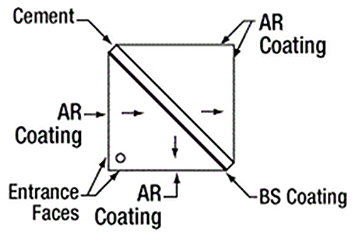
- Non-Polarizing Beam Cube
- Polarizing Beam Cube
- Thorlabs DET 110 photodetector
- Thorlabs DET 10A photodetector
- Thorlabs DET 210 photodetector
- Various optomechanics (mirror mounts, lens holders, baseplates, etc)
- Beam block/alignment tools
- Hecht Optics book
Materials to borrow when necessary
- Oscilloscope
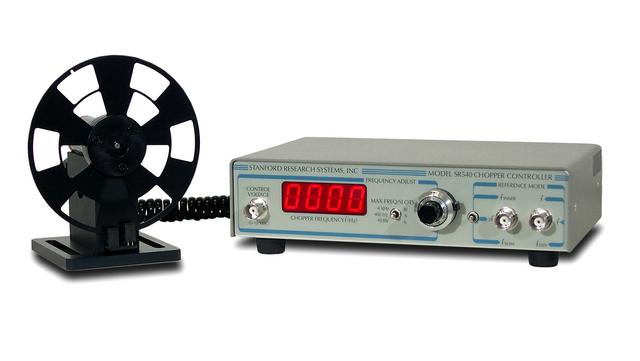
- Chopper
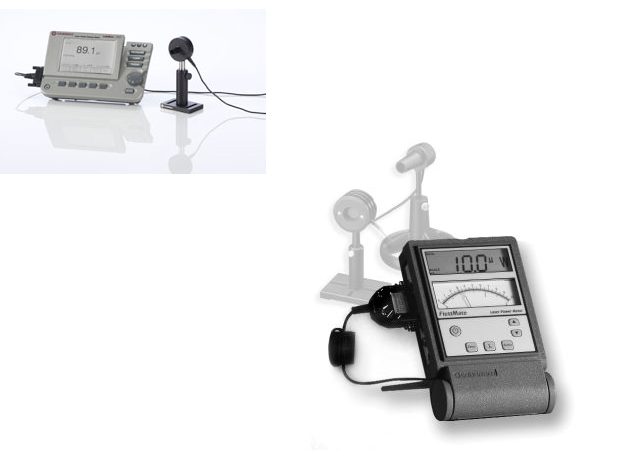
- Power meter
- Extra optics as needed
Activities
You should have the necessary tools at your disposal to complete the following. Instructions are intentionally a bit sparse to encourage thoughtful exploration of the system. The left-hand-side of the optical breadboard is permanent storage for the optics (leave the bases and post holders where they are), and the right-hand-side contains optomechanics you can use in positioning elements in the 'sandbox' area.
Make sure that all the optical components (waveplates, beamcubes, etc.) are designed to work at your laser's wavelength.
- CLEAN UP THE OBSTACLE COURSE SETUP AFTER USE
Keep a journal of your activities, results and answers to any questions asked in the activities below. You will use this for your brief write-up. If any step in the activities below is unclear or you do not completely understand something ask the instructor or TAs for help before moving on.
- Read laser safety, optics common sense, optics hardware info (pages 1-19 of the ebook "Laboratory Optics - A Practical Guide To working in an Optics Lab").
Throughout this exercise, please make an effort to never allow the laser or any reflection/retroreflection leave the boundary of the optical table - Very Important: Get a demonstration/lecture from the instructor or TAs on the proper handling and cleaning of optics. Do not proceed until this is done.
- Read pages 20-31 of Laboratory Optics ebook.
- Read about polarization in the Hecht Optics book. Download and run this applet to explore polarizers. Use two mirrors to set the beam height to a level 4” above optical table. Is the light polarized? If not, polarize it, aligning the axis of polarization vertically.
- Read about Brewster's angle in Hecht. Download and run this applet to explore Brewster's angle.
- Use a glass microscope cover slip on a rotation stage and the laser horizontally polarized to measure Brewster's angle (based on power and/or polarization measurements). From the measured Brewster's angle calculate the cover slip's index of refraction. Calculate the Brewster's angle assuming a glass index of refraction of 1.5. Does your measured Brewster's angle agree?
- Read sections 3.1-3.5 of Laboratory Optics ebook.
- Use mirrors to pass beam through two irises (or two beam alignment cards), aligned along a row of holes on the table.
You now have a level beam with set polarization that is pointing in a known direction. This is an appropriately initialized optical setup. - Read sections 4.1-4.3 of Laboratory Optics ebook.
- Measure the power of the beam using two techniques: a power meter; and the Thorlabs photodetector and an oscilloscope (for this second method, you'll need to look up the responsivity curve on the detector datasheet). These two measurements should be in reasonable agreement. If they're not consult with the instructor or TAs for help. Make sure you're operating the power meter correctly. That is, use the correct power-meter detector head for your wavelength and set the power meter to your specific wavelength. Also make sure you're using an appropriate (electrical) power supply (rated at the correct voltage/current) for the power meter.
- If the photodetector appears to be saturating (detector's output voltage at spec'd maximum), you will need to use neutral density filters to reduce the power.
- For insight to what the numbers on the filters mean, measure the Optical Density (OD) of the blue laser goggles at the HeNe wavelength

Read about half and quarter waveplates (also called retarders in Hecht's Optics) before doing the following:
Download and run this optical polarization applet. Try to create circular and elliptical polarization. If you have trouble ask the instructor to help.
- How does vertically polarized light interact with the polarizing beamsplitter cube? Use the half waveplate to rotate the axis of polarization to be horizontal. Now what happens with the cube? Finally, rotate the axis of polarization to be 45 degrees from vertical
- Align the axis of the quarter waveplate so that the beam is circularly polarized. How do you know it’s circular and not elliptical?
- Build a 1:2 telescope to expand the beam
- Use a 200 micron pinhole, the photodiode and a translation stage (scan the beam in the transverse direction) to measure the 1/e width of the collimated laser beam. See here for info on using translation stages - https://june.uoregon.edu/mediawiki/index.php/How_to_Read_a_Micrometer.
- Draw a simple ray diagram to estimate the magnification you expect for the two supplied lenses
- Be sure to position the lenses so the beam is centered (hint: you should do this by observing the output beam location, not merely by eyeballing where the beam hits the lens)
- Ensure collimation after second lens. Does the magnification match your prediction?
- Place a (suitably chosen - ask instructor) pinhole at the focus of the telescope. Read about Gaussian Laserbeams in Hecht pages 617 to 619. Pay especial attention to the concepts of spot size and Rayleigh range. What is the spot size (take measurements)? What is the Rayleigh range (take measurements)?
- Focus light onto a small (silicon) photodiode (e.g., Thorlabs DET 10A). Use a chopper in between a two-lens telescope and an oscilloscope to measure the rise time of the small diode. Do the rise time measurement again with a larger (silicon) photodiode (e.g., Thorlabs DET 110). Compare the two measured rise times. Are they different? Can you explain? Note: When using the chopper, use a short focal length converging lens to focus the beam (to a small spot) in the plane of the chopper and another lens to re-collimate the beam after the chopper. If this doesn't make sense ask the TA or instructor to explain.
- Use a polarizer and a quarter waveplate to create a "poor man's" optical isolator. Why would this be useful?
- Use a polarizing beamsplitter and a quarter waveplate to make a (slightly) better optical isolator.
- Discuss the drawbacks of the previous two types of isolators. Read about an even better type of isolator that employs a Faraday rotator.
- Use a mini fiber-coupled spectrometer to obtain the center wavelength and an upper bound on the linewidth of the laser. Have a discussion with the TA or instructor about the concept of linewidth.
- Read sections 5.1-5.4 of Laboratory Optics ebook.
- Read about a Michelson interferometer in Hecht Optics. See this page for more infomation. Build a Michelson interferometer (with a non-polarizing beamsplitter) and measure the laser wavelength. Now use the Michelson to measure the index of refraction of 1) a glass microscope slide and 2) an unknown optical material (ask instructor). (Leave the Michelson set up for next activity)
- Read about coherence theory in Hecht's Optics Chpts 12.1, 12.2 and 12.3. Measure the laser's coherence length (ask instructor or TA for help).
- Fabry-Perot (FP) cavities: Read about FP cavities in Hecht sections 9.6 and 9.6.1. Pay attention to the concepts of Finesse, Free Spectral Range (FSR) and Resolution.
- Use the Finesse/Luxor software package (already downloaded and located in the user's home directory on lab computer hank - run Luxor.jar in the FinesseLuxor directory) to simulate a FP cavity. Explore how the cavity Finesse, FSR and Resolution depend upon the mirror reflectivity and mirror spacing.
- Assume the cavity mirrors are planar with a power (not amplitude) reflectivity of 90% (R = 0.9). Calculate the cavity finesse assuming an on-axis light beam.
- Construct a plane-mirror Fabry-Perot with a Free Spectral Range (FSR) of 500MHz and a Finesse >= 20. What is the cavity resolution?
- Construct a plane-mirror Fabry-Perot with a Free Spectral Range (FSR) of 1 GHz and a Finesse >= 20. What is the cavity resolution?
- Is the finesse of your cavity equal to the calculated finesse? If not, why?
- What are the practical limits on the achievable finesse? In other words, what is the limit of achievable cavity resolution?
- Aberrations: Read Hecht Chpt 5.1, 5.2, 5.2.1, 5.2.2, 6.3.1, 6.3.2, (stopping at page 272). Pay especial attention to the concepts of "diffraction-limited", "aspherical surfaces", "spherical surfaces", "optical axis", "aberrations", "paraxial rays", "Gaussian optics", "Seidel aberrations", "spherical aberration", "circle of least confusion", "coma", "astigmatism", "field curvature", "distortion", "chromatic aberrations".
- What type of lens surface will take all rays falling on its surface and focus them to the same point?
- How can a spherical lens be used so that the Seidal aberrations are minimal?
- Download and run this Optica-based CDF file to demonstrate the effects of spherical aberration.
- Download and run this Optica notebook (detailing Seidel aberrations in Mathematica on lab computer hank)
- Debrief with the instructor concerning your efforts, observations and measurements of the obstacle course.
After you finish, please return items to the storage location and clear the 'sandbox' area.
- CLEAN UP THE OBSTACLE COURSE SETUP AFTER USE