Optical Tweezers
Contents
Optical Tweezers
Background
Scattering Basics - Incident Plane Wave (from Michigan Tech)
Plane wave scattering theory may be used to illustrate gross optical trapping behavior via momentum transfer between the light field and the particle (total momentum is conserved). However, the optical waves employed to trap a particle in a typical optical-tweezers setup are most definitely not planar. For a full description of the scattering process see "Theory of trapping forces in optical tweezers", A. Mazolli, P. A. Maia Neto and H. M. Nussenzveig, Proc. R. Soc. Lond., A 8 December 2003 vol. 459 no. 2040 3021-3041.
When the size parameter , where is the particle radius, is the index of the medium surrounding the particle and is the vacuum wavelength of the trapping light, the results from a geometrical optics treatment holds.


For a geometrical optics treatment see, "Optical tweezers for undergraduates: Theoretical analysis and experiments", M. S. Rocha, Am. J. Phys. 77, 704 (2009).
Example: For a trapping laser of wavelength 635nm and a 2 micron particle in a surrounding medium of water, so the geometrical optics treatment holds and Mie scattering is the dominant trapping process.

More simply, there are two forces in action on a trapped particle, one of which will be more dominant depending on the size of the particle, the wavelength, etc. One of these forces is the transference of momentum by photons, the other force is the attractive force of the electric field gradient. The first acts somewhat like a strong current of water, the second draws the particle up to the highest point of the gradient, the center of the laser.

Resources
Making Diluted Solutions of MicroSpheres
- Summer 2014 Powerpoint[1]
- [2] Directions on how to use a QPD in an optical tweezer setup.
- [3] Here are some slide prepping instructions from Berkeley.
Our own setup
- Objective lens alignment & care
- To align the objective lens so that it is mounted parallel to the optical bench surface, use a level on the objective mount.
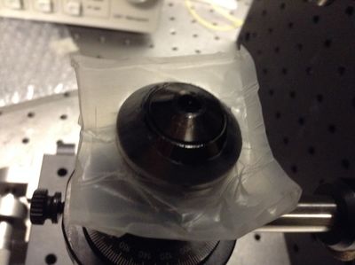
- Make an oil guard to keep immersion oil off the main chassis of the objective by cutting a small hole in the center of a square of Parafilm and pushing the objective through.
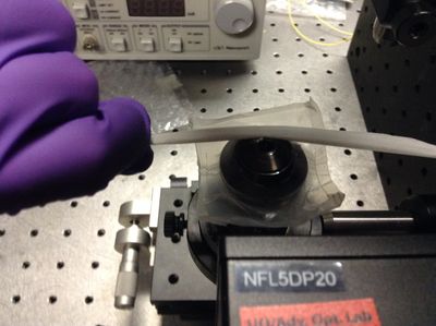
- To remove oil from the objective lens, carefully use a lens tissue around the end of the lens to draw oil off the lens using capillary action without actually touching the delicate output lens.
- Slide Setup
- Microscope Slide Mount
-
Stokes' Setup
- Spring 2013 Method (ramped) [4]
-
Summer 2014 Method (sinusoidal)
[5]
- Stoke's Force Calibration Video (sinusoidal)[6]
Using NI Vision Assistant
- [7] Image Acquisition/Saving Images. The UI for this program is rather difficult. To exit from video capture mode after capturing images there is a button that says close near the bottom left, underneath the camera options window.
-
[8] How to track the microspheres in NI Vision Assistant using pattern matching.
- To get an actual video, you need to run the pictures through another video editing program. There is one on the computer, but there is no video option in NI Vision Assistant itself.
- We actually tried both using pattern matching and brute force point and click methods. Neither worked very well, so we recommend using the QPD to get position measurements. You don't need an actual video for this.
- The pattern matching does work quite well for the purposes of tracking brownian motion. You need to create a pattern matching script and then run it through batch processing.
- During batch processing, pay attention to the red and green tracking squares as the images are being processed. If these squares do not appear, the program is likely not tracking the object position accurately.
- Calibrating the laser so that it points directly at the slide is very important. There are two steps.
- First remove the slide and the objective, then position a pair of (0.5 - 0.75mm) pinholes straight above the objective, and adjust the mirrors until the laser can shoot through both pinholes. That's the rough calibration.
- Next, put the slide and objective back on and adjust the z-axis until you can see the interference patterns the laser makes on the slide. Then adjust (rotate) the objective until the interference patterns are round. Then the laser should be pointed straight at the slide.
Calibration
Our calculations using Brownian Motion
Calculating Trap Forces Using Stokes' Drag Force
- [11] iPython Calculations
-
Beam Power (mW) Escape Velocity (microns/second) Trap Force (pN) 5.5 20.57 0.44 8.5 33.49 0.72 11.7 40.00 0.86 15.3 62.60 1.34 19.0 84.71 1.82 23.0 110.77 2.38 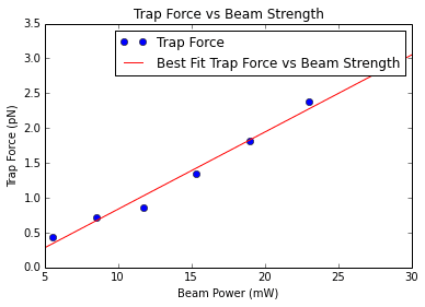
- A simple calculation would say that I need a 10 billion watt laser to achieve a 1 Newton trapping force. We should totally do that. The spheres would be so incredibly trapped.
Trapping Video
Performing Biological Measurements
- Installing Infared Laser
- Preparing bacteria to Analyze
- Current Progress and Issues


Vortex Wave Retarder
- Summer 2016 Powerpoint[13]