Electronics Obstacle Course
Permanent Materials (located in the electronics area):
- power supplies
- function generators
- oscilloscopes
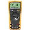
- multimeters (MMs)
- capacitance meter
- electronic proto-boards
- wire, resistors, capacitors, inductors, diodes, Op-Amps, other ICs
- photodiodes (PDs), light-emitting diodes (LEDs), laser diodes (LDs)
- soldering equipment and supplies
Materials to borrow when necessary
- LTSpice circuit simulation software
- lab copy of The Art of Electronics, Horowitz & Hill
- inductance meter
- Keithley voltage supply
Activities
- If you have zero electronic training or experience read chapters 1-6 of Keith Brindley's eBook Starting Electronics.
- If you have some small experience with electronics proceed and consult Starting Electronics or The Art of Electronics as needed.
Resistor & Capacitor Basics
- With a MM measure the resistance of five 100 Ohm resistors. Do they fall within the specified tolerance?
- What is resistance? Can you provide an analogy based on water flowing through pipes?
- Is energy stored in a resistor or dissipated as heat? Can you provide an explanation of the basic physical processes?
- What is the resistance of two 100 Ohm resistors in series? How do resistors in series add?
- What is the resistance of two 100 Ohm resistors in parallel? How do resistors in parallel add?
- How does the MM measure the resistance?
- What can you say about the "internal" resistance of the MM in resistance measurement mode?
- Using a proto-board and one of the 100 Ohm resistors put 2.5VDC across the resistor. Calculate the current. Use the MM in ammeter mode to measure the current. Are the calculated and measured values close? Does the power applied to the resistor fall within the power rating of the resistor? What is power? What could happen if you applied too much power to the resistor?
- What is current?
- How does the MM measure current?
- What can you say about the "internal" resistance of the ammeter used in the measurement of the current?
- How do the MM wire leads effect these measurements?
- Could you measure the resistance of a 1cm length of copper wire with the MM? Why?
- Put 100mA of DC current through a 10 Ohm resistor.
- What power is being applied to the resistor? Calculate the voltage across the resistor. With the MM measure the voltage across the resistor. Are these values close?
- What is voltage?
- How does the MM measure a voltage?
- What can you say about the MM's "internal" resistance when it measures a voltage?
- With a function generator put a 2.5VAC (peak-to-peak) sinusoidal voltage at frequencies of 50, 500 and 1000Hz across a 100 Ohm resistor.
- Using the MM in voltage mode measure the AC voltage. Does it vary with frequency?
- Using the MM in current mode measure the AC current. Does it vary with frequency?
- Measure the capacitance of five 0.1 f unpolarized capacitors. Do they fall within the specified tolerance?
- What is capacitance? Describe physically a very simple capacitor.
- How is energy stored in a capacitor?
- What is the difference between unpolarized and polarized capacitors?
- What is the capacitance of two 0.1 f capacitors in series? How do capacitors in series add?
- What is the capacitance of two 0.1 f capacitors in parallel? How do capacitors in parallel add?
- How does the capacitance meter measure the capacitance?
- Using a proto-board apply 2.5VDC across an 0.1 f capacitor and 100 Ohm resistor in series. Using a MM measure the voltage across the entire capacitor + resistor series network. Measure the voltage across the capacitor only. Measure the voltage across the resistor only. Explain the measured voltage across the resistor.
- Now apply a 2.5VAC sinusoidal voltage across the capacitor + resistor network at 50, 500 and 1000 Hz.
- What's the voltage across the resistor for 50, 500 and 1000Hz?
- What's the voltage across the capacitor for 50, 500 and 1000Hz?
- How does the voltage across the capacitor as a function of frequency compare to the voltage across a resistor as a function of frequency?
- Build a network of two (possibly different valued) resistors that takes an input voltage of 5VDC and produces an output voltage at 2.5VDC.
- Build a network of two (possibly different valued) resistors that takes an input voltage of 5VDC and produces an output voltage at 1.25VDC.
- Build a network of an f capacitor and a 100 Ohm resistor in series.
- Apply a 1VAC sinusoidal (input) signal to the capacitor at 100, 1000, 5000, 10000, 15000, 20000, 25000 and 50000 Hz and measure the (output) voltage between the capacitor and the resistor for each frequency.
- Plot as a function of frequency. What can you say about the frequency dependence of the ratio of output to input voltage?
- You've just built three very useful circuits called voltage dividers. Would a voltage divider containing only resistors work for AC voltages? If you're unsure, try it. Would a voltage divider containing at least one capacitor work for DC voltages? Again, if you're unsure, try it.
- Now, apply a 1V 10Hz square pulse to a 500 Ohm resistor and an 470 f capacitor in parallel.
- Using an oscilloscope measure the voltage across the capacitor + resistor parallel network. (You'll need to use the oscilloscope's front-panel controls to get the waveform on the screen and get the triggering to work)
- Are the leading and trailing edges of the pulse similar? Why?
- What is the "rise time" of the leading edge (10% to 90%)?
- What is the "fall time" of the trailing edge (10% to 90%)?
- What is the time it takes for the trailing edge to fall to 1/e of its initial value?
- What is the value of the resistance multiplied by the capacitance?
- Next let's use resistors and a capacitors to build one frequency-low-pass circuit and one frequency-high-pass circuit.
- Use what you've learned about the AC and DC responses of capacitors and resistors to put together a resistor + capacitor network that blocks DC current, strongly attenuates low frequencies but passes high frequencies (hint: recall the voltage divider of 7 above).
- Determine the circuit's 3dB point.
- Put together a resistor + capacitor network that passes DC current and low frequencies but strongly attenuates high frequencies.
- Determine the circuit's 3dB point.
Inductor Basics
- Measure the inductance of five 1mH inductors. Estimate their tolerance (5%, 10%, 15% or 20%).
- What is inductance? Describe physically a very simple inductor.
- How is energy stored in an inductor?
- What is the inductance of two 1mH inductors in series? How do inductors add in series?
- What is the inductance of two 1mH inductors in parallel? How do inductors add in parallel?
- Do inductors add like resistors or capacitors?
- How does the inductance meter measure inductance?
- Using a proto-board apply 1VDC across a 1mH inductor and 500 Ohm resistor in series. Using a MM measure the voltage across the entire inductor + resistor series network. What is the inductors "resistance" in this situation?
- Put a 1VAC sinusoidal signal across the inductor + resistor network at 50, 500, 2kHz, 5kHz and 10kHz, 25kHz, 50000, 250kHz and 1Mhz.
- At each frequency measure the voltage across the inductor only. Measure the voltage across the resistor only. Explain the measured voltage across the resistor in terms of how the inductor behaves with frequency.
- At each frequency measure the voltage across the inductor only. Measure the voltage across the resistor only. Explain the measured voltage across the resistor in terms of how the inductor behaves with frequency.
Resonant circuits
- Construct the circuit shown at the right using a 100 Ohm resistor, 1mH inductor and a 10uf capacitor.
- Apply a 1VAC sinusoidal input voltage at frequencies between 10 and 3000Hz and plot the output voltage as a function of frequency.
- At what frequency is the response of the circuit maximum?
- Explain the response of this circuit based on what you've learned about capacitors and inductors.
- When would a circuit with a response like this be useful?
- Can you think of an optical-cavity analogy?
Impedance and Reactance
Impedance is resistance generalized. A resistor resists (dissipates power) but does not change the waveform (square wave in square wave out). Capacitors and inductors (since they store energy) can react and cause changes in the waveform (see section 8 above).
The concept of impedance includes resistance and reactance effects. That is, Impedance = Resistance + Reactance. All the frequency dependence is contained within the reactance. For ideal capacitors and inductors their resistance is zero (not the case in real life). An ideal resistor is a purely resistive component and has no reactance (again, not the case in real life).
We can use the word "impedance" in general. When we say something like, "What's the resistor's impedance", we are referring to the resistance term of the resistor's impedance equation. When we say something like, "What's the impedance of the capacitor", we are referring to the reactance term of the capacitor's impedance equation.
- Think back to the previous exercises.
- What is the frequency dependence of a capacitor's impedance?
- What is the frequency dependance of an inductors impedance?
Diodes
For the electronic components considered above (resistor, capacitor, inductor) it doesn't matter which way you put them into a circuit - they are non-directional. That is, you can flip their leads and the circuit will behave the same. For diodes this is not the case. Diodes are directional and it matters which way they are oriented in a circuit. Diodes are physically more complicated than the components treated above so we won't go into an explanation of just what a diode is now. We'll only consider how diodes behave.
- Put a P6KE6.8 diode in series with a MM in ammeter mode and ground the anode.
- Apply 0.7VDC to the cathode and measure the current through the diode.
- Now ground the cathode and apply 0.7VDC to the anode and measure the current through the diode.
- Are the currents the same?
- With the cathode grounded apply voltages from 0-1.5 VDC to the anode in 0.1 V increments and plot the result. This is the forward I-V curve for the diode. The diode is said to be "forward biased" in this situation.
- There should be a "knee" in this curve where the diode "turns on" or conducts. About what voltage is this?
- Using the (current limited) Keithley voltage supply, apply voltages from 0-100VDC to the anode grounded diode and plot the result. This is the reverse I-V curve for the diode. The diode is said to be "reverse biased" in this situation.
- There should be a "knee" in this curve too where the diode starts to conduct in the reverse direction. About what voltage is this?
- Are the forward and reverse "turn on" voltages symmetric about 0V?
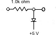
- Construct the diode clamp circuit shown at the right.
- Apply input voltages from 0-10VDC and plot the output voltage vs. input voltage.
- Does the diode clamp earn its name?
- Can you explain the maximum output voltage?
Transistors
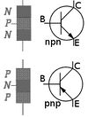
All the components (even diodes) examined above are considered "passive" components. That is, they can't supply energy. Transistors are considered "active" in the sense that they can supply energy (or amplify). Like diodes, transistors are physically more complicated than resistors, capacitors and inductors and we won't go into detail about just what they are. Instead we'll focus on how transistors behave. The collector C must be biased more positive than the emitter E. The current through the collector IC is roughly proportional to the current into the base IB (usually anywhere from 50 to 250 times IB). So there you have it. In a first approximation the transistor is a current amplifier. A small current flowing into the base controls a much larger current flowing into the collector.
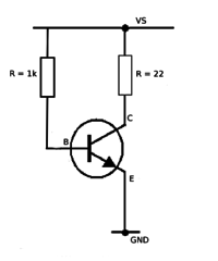
- Ground the emitter of a TIP31C npn transistor. Put a 22 Ohm resistor in parallel with a MM in ammeter mode between the collector and a +2.5VDC supply. Put a 1kOhm resistor in series with an ammeter between the base and the +2.5VDC supply.
- Measure the collector current and the base current for supply voltages VS between 1.25 to 3VDC.
- Plot IC/IB vs. VS.
- What is the proportionality factor between IC and IB at VS = 1.25VDC?
- Is the proportionality factor independent of VS ?
- Does the transistor amplify current?
Operational Amplifiers (OpAmps)
OpAmps are integrated circuits (ICs) that contain within them many transistors, resistors, capacitors and possibly diodes miniaturized into a single IC component.
OpAmps are very high gain dc-coupled differential amplifiers with single-ended outputs and are usually employed with feedback.
The OpAmp we will be using is National semiconductor's general purpose LM741. OpAmp behaviour can may be simplified into two simple rules.
- The output attempts to do whatever is necessary to make the voltage difference between the inputs zero.
- The inputs draw no (very little anyway) current.
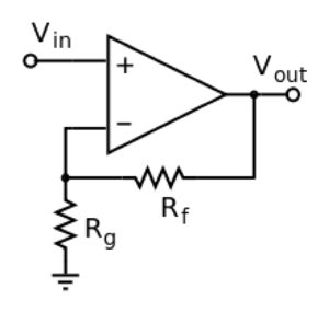
- Use an LM741, a 1kOhm and a 500Ohm resistor to construct the non-inverting amplifier shown at the right (power to OpAmp not shown).
- Power the OpAmp at +10VDC and -10VDC.
- Apply a +1VDC signal to the input and measure the output voltage.
- Can you explain the OpAmps behaviour in terms of the first rule above?
- What is the gain of your amplifier (Vout/Vin)?
- What is the value of 1 + Rf/Rg?
- Are these last two values the same?
- Replace Rf with Rg and Rg with Rf.
- Apply a +1VDC signal to the input and measure the output voltage.
- What is the gain of your amplifier (Vout/Vin)?
- What is the value of 1 + Rf/Rg (remember you switched the values of Rf and Rg)?
- What is the general formula for the gain of a non-inverting amplifier?
- Reconfigure the LM741, the 1kOhm and 500Ohm resistors for an inverting amplifier (see diagram at right).
- Apply a +1VDC input and measure the output.
- Can you explain the OpAmps behaviour in terms of the first rule above?
- What is the gain of your amplifier (Vout/Vin)?
- What is the value of -Rf/Rin
- Are these last two values the same?
- Switch Rf and Rin.
- Apply a -1VDC signal to the input and measure the output voltage.
- What is the gain of your amplifier (Vout/Vin)?
- What is the value of -Rf/Rin (remember you switched the values of Rf and Rin)?
- What is the general formula for the gain of an inverting amplifier?
Instrumentation and Loading
Since electronic instruments (MMs, oscilloscopes, function generators, even Opamps, etc.) are composed of resistors, capacitors, inductors, diodes, transistors, OpAmps, etc., they have characteristic net input and output impedances.
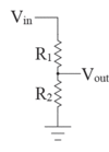
Consider the simple voltage divider circuit shown at the right.
Let Vin be 10VDC and R1 = R2 = 10MOhm. Based on your experience in section 5 above what do you think Vout should be?
- Construct the voltage divider.
- Let R1 = R2 = 1kOhms. Measure Vout. Is Vout what you expected?
- Change both resistors to 10kOhm. Measure Vout. Is Vout what you expected?
- Change both resistors to 500kOhm. Measure Vout. Is Vout what you expected?
- Change both resistors to 1MOhm. Measure Vout. Is Vout what you expected?
- Change both resistors to 10MOhm. Measure Vout. Is Vout what you expected?
- What do you think is going on? Remember how the MM measures voltage.
This voltage sagging effect is the result of circuit loading. The MM bleeds off a small bit of the current and runs it through a very precise calibrated large value resistor (usually between 1MOhm and 10MOhms). When R2 is 1kOhm the MM bleeds off a very small fraction of the current that should have flowed through R2. Consequently, the measured voltage at Vout sags minimally. However, as R2 increases to values approaching the MM's "internal" resistance (or input impedance) the MM draws off larger and larger fractions of the current that should have run through R2. Consequently, the measured voltage at Vout sags substantially.
The voltage divider and MM can be thought of as a two stage electrical device. The first stage does something and then "hands off" the result to the second stage which also does something.
What can you say about the output impedance of a first-stage electronic device in relation to the input impedance of a second-stage electronic device?
