Difference between revisions of "Electronics Obstacle Course"
| Line 21: | Line 21: | ||
=== Activities === | === Activities === | ||
| − | ==== | + | * If you have zero electronic training or experience read chapters 1-6 of Keith Brindley's eBook ''Starting Electronics''. |
| + | * If you have some small experience with electronics proceed and consult ''Starting Electronics'' or ''The Art of Electronics'' as needed.<br> | ||
| + | |||
| + | ==== Resistor & Capacitor Basics ==== | ||
| + | |||
| − | |||
| − | |||
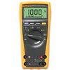
[[File:Fluke_179.jpg|right|100px| thumb| multimeter]] | [[File:Fluke_179.jpg|right|100px| thumb| multimeter]] | ||
# With a MM measure the resistance of five 100 Ohm resistors. Do they fall within the specified tolerance? | # With a MM measure the resistance of five 100 Ohm resistors. Do they fall within the specified tolerance? | ||
| − | ## What is resistance? | + | ## What is resistance? Can you provide an analogy based on water flowing through pipes? |
| + | ## Is energy stored in a resistor or dissipated as heat? Can you provide an explanation of the basic physical processes? | ||
## What is the resistance of two 100 Ohm resistors in series? How do resistors in series add? | ## What is the resistance of two 100 Ohm resistors in series? How do resistors in series add? | ||
## What is the resistance of two 100 Ohm resistors in parallel? How do resistors in parallel add? | ## What is the resistance of two 100 Ohm resistors in parallel? How do resistors in parallel add? | ||
| Line 47: | Line 50: | ||
## Using the MM in current mode measure the AC current. Does it vary with frequency?<br><br><br> | ## Using the MM in current mode measure the AC current. Does it vary with frequency?<br><br><br> | ||
# Measure the capacitance of five 0.1 <math>\mu</math>f unpolarized capacitors. Do they fall within the specified tolerance? | # Measure the capacitance of five 0.1 <math>\mu</math>f unpolarized capacitors. Do they fall within the specified tolerance? | ||
| − | ## What is capacitance? | + | ## What is capacitance? Describe physically a very simple capacitor. |
| + | ## How is energy stored in a capacitor? | ||
## What is the difference between unpolarized and polarized capacitors? | ## What is the difference between unpolarized and polarized capacitors? | ||
## What is the capacitance of two 0.1 <math>\mu</math>f capacitors in series? How do capacitors in series add? | ## What is the capacitance of two 0.1 <math>\mu</math>f capacitors in series? How do capacitors in series add? | ||
| Line 75: | Line 79: | ||
## Put together a resistor + capacitor network that passes DC current and low frequencies but strongly attenuates high frequencies. | ## Put together a resistor + capacitor network that passes DC current and low frequencies but strongly attenuates high frequencies. | ||
## Determine the circuit's 3dB point.<br><br><br> | ## Determine the circuit's 3dB point.<br><br><br> | ||
| − | # | + | |
| + | ==== Inductor Basics ==== | ||
| + | [[File:Inductor_symbol.png|thumb|100px|right|Inductor Symbol- L]] | ||
| + | # Measure the inductance of five 1mH inductors. Estimate their tolerance (5%, 10%, 15% or 20%). | ||
| + | ## What is inductance? Describe physically a very simple inductor. | ||
| + | ## How is energy stored in an inductor? | ||
| + | ## What is the inductance of two 1mH inductors in series? How do inductors add in series? | ||
| + | ## What is the inductance of two 1mH inductors in parallel? How do inductors add in parallel? | ||
| + | ## Do inductors add like resistors or capacitors? | ||
| + | ## How does the inductance meter measure inductance?<br> | ||
| + | # Using a proto-board apply 1VDC '''across''' a 1mH inductor and 500 Ohm resistor in series. Using a MM measure the voltage '''across''' the entire inductor + resistor series network. What is the inductors "resistance" in this situation? | ||
| + | # Put a 1VAC sinusoidal signal across the inductor + resistor network at 50, 500, 2kHz, 5kHz and 10kHz, 25kHz, 50000, 250kHz and 1Mhz. | ||
| + | ## At each frequency measure the voltage across the inductor only. Measure the voltage across the resistor only. Explain the measured voltage across the resistor in terms of how the inductor behaves with frequency.<br><br><br> | ||
| + | ==== Resonant circuits ==== | ||
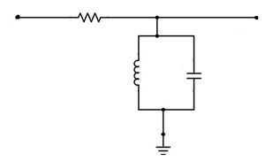
| + | [[File:LR_Bandpass_filter.jpg|thumb|right|LC resonant circuit - bandpass filter]] | ||
| + | # Construct the circuit shown at the right using a 100 Ohm resistor, 1mH inductor and a 10uf capacitor. | ||
| + | ## Apply a 1VAC sinusoidal input voltage at frequencies between 10 and 3000Hz and plot the output voltage as a function of frequency. | ||
| + | ## Explain the response of this circuit based on what you've learned about capacitors and inductors. | ||
| + | ## When would a circuit with a response like this be useful? | ||
Revision as of 11:18, 10 February 2015
Contents
Permanent Materials (located in the electronics area):
- power supplies
- function generators
- oscilloscopes
- multimeters (MMs)
- capacitance meter
- electronic proto-boards
- wire, resistors, capacitors, inductors, diodes, Op-Amps, other ICs
- photodiodes (PDs), light-emitting diodes (LEDs), laser diodes (LDs)
- soldering equipment and supplies
Materials to borrow when necessary
- LTSpice circuit simulation software
- lab copy of The Art of Electronics, Horowitz & Hill
- inductance meter
Activities
- If you have zero electronic training or experience read chapters 1-6 of Keith Brindley's eBook Starting Electronics.
- If you have some small experience with electronics proceed and consult Starting Electronics or The Art of Electronics as needed.
Resistor & Capacitor Basics
- With a MM measure the resistance of five 100 Ohm resistors. Do they fall within the specified tolerance?
- What is resistance? Can you provide an analogy based on water flowing through pipes?
- Is energy stored in a resistor or dissipated as heat? Can you provide an explanation of the basic physical processes?
- What is the resistance of two 100 Ohm resistors in series? How do resistors in series add?
- What is the resistance of two 100 Ohm resistors in parallel? How do resistors in parallel add?
- How does the MM measure the resistance?
- What can you say about the "internal" resistance of the MM in resistance measurement mode?
- Using a proto-board and one of the 100 Ohm resistors put 2.5VDC across the resistor. Calculate the current. Use the MM in ammeter mode to measure the current. Are the calculated and measured values close? Does the power applied to the resistor fall within the power rating of the resistor? What is power? What could happen if you applied too much power to the resistor?
- What is current?
- How does the MM measure current?
- What can you say about the "internal" resistance of the ammeter used in the measurement of the current?
- How do the MM wire leads effect these measurements?
- Could you measure the resistance of a 1cm length of copper wire with the MM? Why?
- Put 100mA of DC current through a 10 Ohm resistor.
- What power is being applied to the resistor? Calculate the voltage across the resistor. With the MM measure the voltage across the resistor. Are these values close?
- What is voltage?
- How does the MM measure a voltage?
- What can you say about the MM's "internal" resistance when it measures a voltage?
- With a function generator put a 2.5VAC (peak-to-peak) sinusoidal voltage at frequencies of 50, 500 and 1000Hz across a 100 Ohm resistor.
- Using the MM in voltage mode measure the AC voltage. Does it vary with frequency?
- Using the MM in current mode measure the AC current. Does it vary with frequency?
- Measure the capacitance of five 0.1 f unpolarized capacitors. Do they fall within the specified tolerance?
- What is capacitance? Describe physically a very simple capacitor.
- How is energy stored in a capacitor?
- What is the difference between unpolarized and polarized capacitors?
- What is the capacitance of two 0.1 f capacitors in series? How do capacitors in series add?
- What is the capacitance of two 0.1 f capacitors in parallel? How do capacitors in parallel add?
- How does the capacitance meter measure the capacitance?
- Using a proto-board apply 2.5VDC across an 0.1 f capacitor and 100 Ohm resistor in series. Using a MM measure the voltage across the entire capacitor + resistor series network. Measure the voltage across the capacitor only. Measure the voltage across the resistor only. Explain the measured voltage across the resistor.
- Now apply a 2.5VAC sinusoidal voltage across the capacitor + resistor network at 50, 500 and 1000 Hz.
- What's the voltage across the resistor for 50, 500 and 1000Hz?
- What's the voltage across the capacitor for 50, 500 and 1000Hz?
- How does the voltage across the capacitor as a function of frequency compare to the voltage across a resistor as a function of frequency?
- Build a network of two (possibly different valued) resistors that takes an input voltage of 5VDC and produces an output voltage at 2.5VDC.
- Build a network of two (possibly different valued) resistors that takes an input voltage of 5VDC and produces an output voltage at 1.25VDC.
- Build a network of an f capacitor and a 100 Ohm resistor in series.
- Apply a 1VAC sinusoidal (input) signal to the capacitor at 100, 1000, 5000, 10000, 15000, 20000, 25000 and 50000 Hz and measure the (output) voltage between the capacitor and the resistor for each frequency.
- Plot as a function of frequency. What can you say about the frequency dependence of the ratio of output to input voltage?
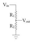
- You've just built three very useful circuits called voltage dividers. Would a voltage divider containing only resistors work for AC voltages? If you're unsure, try it. Would a voltage divider containing at least one capacitor work for DC voltages? Again, if you're unsure, try it.
- Now, apply a 1V 10Hz square pulse to a 500 Ohm resistor and an 470 f capacitor in parallel.
- Using an oscilloscope measure the voltage across the capacitor + resistor parallel network. (You'll need to use the oscilloscope's front-panel controls to get the waveform on the screen and get the triggering to work)
- Are the leading and trailing edges of the pulse similar? Why?
- What is the "rise time" of the leading edge (10% to 90%)?
- What is the "fall time" of the trailing edge (10% to 90%)?
- What is the time it takes for the trailing edge to fall to 1/e of its initial value?
- What is the value of the resistance multiplied by the capacitance?
- Next let's use resistors and a capacitors to build one frequency-low-pass circuit and one frequency-high-pass circuit.
- Use what you've learned about the AC and DC responses of capacitors and resistors to put together a resistor + capacitor network that blocks DC current, strongly attenuates low frequencies but passes high frequencies (hint: recall the voltage divider of 7 above).
- Determine the circuit's 3dB point.
- Put together a resistor + capacitor network that passes DC current and low frequencies but strongly attenuates high frequencies.
- Determine the circuit's 3dB point.
Inductor Basics
- Measure the inductance of five 1mH inductors. Estimate their tolerance (5%, 10%, 15% or 20%).
- What is inductance? Describe physically a very simple inductor.
- How is energy stored in an inductor?
- What is the inductance of two 1mH inductors in series? How do inductors add in series?
- What is the inductance of two 1mH inductors in parallel? How do inductors add in parallel?
- Do inductors add like resistors or capacitors?
- How does the inductance meter measure inductance?
- Using a proto-board apply 1VDC across a 1mH inductor and 500 Ohm resistor in series. Using a MM measure the voltage across the entire inductor + resistor series network. What is the inductors "resistance" in this situation?
- Put a 1VAC sinusoidal signal across the inductor + resistor network at 50, 500, 2kHz, 5kHz and 10kHz, 25kHz, 50000, 250kHz and 1Mhz.
- At each frequency measure the voltage across the inductor only. Measure the voltage across the resistor only. Explain the measured voltage across the resistor in terms of how the inductor behaves with frequency.
- At each frequency measure the voltage across the inductor only. Measure the voltage across the resistor only. Explain the measured voltage across the resistor in terms of how the inductor behaves with frequency.
Resonant circuits
- Construct the circuit shown at the right using a 100 Ohm resistor, 1mH inductor and a 10uf capacitor.
- Apply a 1VAC sinusoidal input voltage at frequencies between 10 and 3000Hz and plot the output voltage as a function of frequency.
- Explain the response of this circuit based on what you've learned about capacitors and inductors.
- When would a circuit with a response like this be useful?


