Difference between revisions of "Mode-locked Erbium-Ytterbium Doped Fiber Laser"
Aplstudent (talk | contribs) (→The Kerr effect) |
|||
| (21 intermediate revisions by 2 users not shown) | |||
| Line 1: | Line 1: | ||
== High Power Pulsed Fiber Lasers == | == High Power Pulsed Fiber Lasers == | ||
| − | + | [http://www.rp-photonics.com/highpowerfiberlasers.html High Power Fiber Lasers] | |
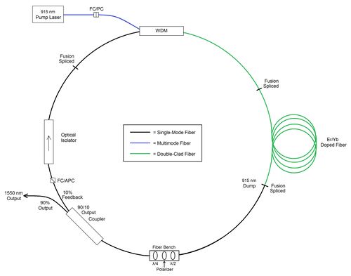
| − | [[File:RingLaser.jpg|500px]] | + | [[File:RingLaser.jpg|thumb|500px|Ring cavity Er-Yb doped fiber laser showing optical bench for Kerr mode locking]] |
| + | |||
| + | Compared to bulk solid-state lasers, the chief advantage of fiber lasers is their outstanding heat-dissipation capability, which is due to the large ratio of surface to volume of such a long, thin gain medium. Fiber lasers and amplifiers have a very high single-pass gain and therefore low laser thresholds and can be efficiently pumped with diode lasers. Moreover, the broad gain bandwidth, the compactness, robustness and simplicity of operation make fiber lasers attractive for a host of applications. Rare-earth-doped PCFs offer several unique properties, which allow an upward scaling of the performance compared to conventional fiber lasers. Their main advantages are the very high pump core NA and an extended possible mode area of truly single-mode cores. | ||
| + | |||
| + | In the pulsed regime, nonlinear processes play a more dominant role and restrict power and energy scaling. However, rare-earth-doped fiber offer features which make them even look promising in this challenging operation regime. The high single-pass gain allows for simple amplification schemes, instead of multi-pass or regenerative amplification, and the average power scalability makes fiber based short-pulse laser systems interesting for applications which ask for high energies in combination with high repetition rates. | ||
== Mode Locking == | == Mode Locking == | ||
| − | Mode locking is a technique to create very short periodic pulses by locking modes in phase | + | [https://en.wikipedia.org/wiki/Mode-locking Mode Locking] |
| + | |||
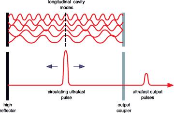
| + | [[File:ModeLocking.jpg|thumb|500px| Mode locking is a technique to create very short periodic pulses by locking modes in phase]] | ||
| + | |||
| + | In a simple laser, each of the longitudinal modes oscillates independently, with no fixed relationship between each other, in essence like a set of independent lasers all emitting light at slightly different frequencies. The individual phase of the light waves in each mode is not fixed, and may vary randomly due to such things as thermal changes in materials of the laser. In lasers with only a few oscillating modes, interference between the modes can cause beating effects in the laser output, leading to fluctuations in intensity; in lasers with many thousands of modes, these interference effects tend to average to a near-constant output intensity. | ||
| + | |||
| + | If instead of oscillating independently, each mode operates with a fixed phase between it and the other modes, the laser output behaves quite differently. Instead of a random or constant output intensity, the modes of the laser will periodically all constructively interfere with one another, producing an intense burst or pulse of light. Such a laser is said to be 'mode-locked' or 'phase-locked'. These pulses occur separated in time by τ = 2L/c, where τ is the time taken for the light to make exactly one round trip of the laser cavity. This time corresponds to a frequency exactly equal to the mode spacing of the laser, Δν = 1/τ. | ||
| − | + | The duration of each pulse of light is determined by the number of modes which are oscillating in phase (in a real laser, it is not necessarily true that all of the laser's modes will be phase-locked). If there are N modes locked with a frequency separation Δν, the overall mode-locked bandwidth is NΔν, and the wider this bandwidth, the shorter the pulse duration from the laser. | |
== Passive Mode Locking == | == Passive Mode Locking == | ||
| Line 21: | Line 31: | ||
== Additive-pulse Mode Locking == | == Additive-pulse Mode Locking == | ||
| − | + | [http://www.rp-photonics.com/active_mode_locking.html Active mode locking] | |
| + | |||
| + | [[File:ModeLocking2.jpg|thumb|500px|Additive pulse mode locking]] | ||
| + | |||
| + | The principle of active mode locking by modulating the resonator losses (AM mode locking) is easy to understand. A pulse with the “correct” timing can pass the modulator at times where the losses are at a minimum. Still, the wings of the pulse experience a little attenuation, which effectively leads to (slight) pulse shortening in each round trip, until this pulse shortening is offset by other effects (e.g. gain narrowing) which tend to broaden the pulse. | ||
| + | |||
| + | For stable operation, the round-trip time of the resonator must fairly precisely match the period of the modulator signal (or some integer multiple of it), so that a circulating pulse can always pass the modulator at a time with minimum losses. Even a small frequency mismatch between the laser resonator and the drive signal can lead to a strong timing jitter or even to chaotic behavior. | ||
| + | |||
| + | Synchronization between the modulator driver and the laser can be achieved either by careful adjustment of a stable laser setup, or by means of a feedback circuit which automatically adjusts either the modulation frequency or the length of the laser resonator. | ||
| + | |||
| + | The principle used in our fiber laser mode locking are: | ||
| − | + | - Nonlinear phase shifts in a single-mode fiber proportional to the intensity of the signal. | |
| − | + | - Pulses returning from the fiber resonator into the main laser resonator interfere with those pulses which already are in the main resonator. | |
| − | + | - Constructive interference near the peak of the pulses, but not in the wings, because the latter have acquired different nonlinear phase shifts in the fiber. | |
| − | + | - Peak of the circulating pulse is enhanced, whereas the wings are attenuated. | |
| − | == | + | == Kerr Mode Locking == |
[http://www.rp-photonics.com/kerr_effect.html Kerr Effect] | [http://www.rp-photonics.com/kerr_effect.html Kerr Effect] | ||
| Line 39: | Line 59: | ||
This uses a nonlinear optical process, the optical Kerr effect, which results in high-intensity light being focussed differently from low-intensity light. By careful arrangement of optics in the laser cavity, this effect can be exploited to produce the equivalent of an ultra-fast response time saturable absorber. | This uses a nonlinear optical process, the optical Kerr effect, which results in high-intensity light being focussed differently from low-intensity light. By careful arrangement of optics in the laser cavity, this effect can be exploited to produce the equivalent of an ultra-fast response time saturable absorber. | ||
| − | Nonlinear polarization generated in the medium, which modifies the propagation properties of the light | + | Nonlinear polarization is generated in the medium, which modifies the propagation properties of the light. |
| − | |||
| − | |||
| − | |||
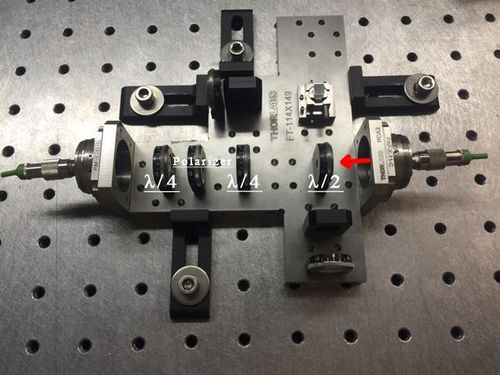
- half wave plate rotates polarization so that the fast axis (highest intensity)is in line with the polarizer; | - half wave plate rotates polarization so that the fast axis (highest intensity)is in line with the polarizer; | ||
| Line 56: | Line 73: | ||
[[File:OpticalBench.jpg|500px]] | [[File:OpticalBench.jpg|500px]] | ||
| + | == Non-Linear Effects and Dispersion == | ||
| + | |||
| + | Two effects play a role in the shaping of pulses in cavity. The first, group velocity dispersion (GVD) is a material property where higher frequency components of the pulse travel slower than lower frequency components for positive, normal dispersion, as seen in the Er-Yb doped fiber. The dispersion for such co-doped fibers has not seen considerable mention in publications, besides one study that claims a value of 0.012 ps^2/m [3]. Many publications reporting on Er doped fibers quote dispersion values between 0.040 ps^2/m [4] and 0.075ps^2/m [5]. Our study starts with a more conservative estimate for the co-doped double-clad fiber of $0.031 ps^2/m. Negative, anomalous dispersion occurs in passive fibers where core is greater than 1.3 micrometers [1]. The Corning SMF-28 fiber used in this investigation has a core of 1.5 micrometers with a widely published GVD around -0.021 ps^2/m [3], [4], [5], [6]. | ||
| + | |||
| + | While material GVD introduces spectral compression and expansion as the pulse travels through the normal and anomalous dispersion fibers, an intensity dependent nonlinear phase shift also contributes to pulse shaping via the Kerr effect. With time dependent intensity, a pulse will experience a time and intensity dependent refractive index, n_NL, governed by | ||
| + | |||
| + | <math>n_{NL} = n_0 + In_2</math> | ||
| + | |||
| + | where n_0 is the material index of a medium, and n_2 is the nonlinear index coefficient and I is the pulse intensity [7]. With the pulse traveling with elliptical polarization through the cavity, this effect causes the vertical and horizontal polarization components to experience different phase shifts. This effect functions like material birefringence which causes a similar differential group delay, resulting in polarization mode dispersion and a rotation of the elliptical polarization which increases linearly with the length of the fiber [8]. As such, the half-wave plate is appropriately rotated to align the rotated ellipse to the polarizing element that functionally trims the pulse. The Kerr nonlinearity additionally causes self-phase modulation (SPM), which causes spectral broadening in anomalous fibers and balances spectral compression due to negative GVD. In normal dispersion fibers, like the co-doped active fiber used in our cavity, SPM functions independently of GVD [3]. The magnitude of SPM increases with length of propagation, and left unbalanced it can cause spectral oscillations and instability. | ||
| + | |||
| + | |||
| + | == Pulse Regimes == | ||
| + | When ratio of passive to active fiber in cavity yields net zero or negative dispersion, a soliton pulse will form. Solitons are self stabilizing and maintain their spectral and temporal shape | ||
| + | throughout the entire cavity due to the balance of GVD and | ||
| + | SPM in the passive fiber. Solitons are commonly achieved when the length of the passive fiber is larger than that of the active | ||
| + | to avoid significant nonlinearity [9]. Even with their inherent | ||
| + | stability, a soliton is limited by the loss of intensity to pulse sidebands. | ||
| + | When the temporal shape of a soliton is compressed, the | ||
| + | pulse loses intensity to the sidebands. This is undesirable when | ||
| + | constructing a pulsed laser for high peak power and minimal | ||
| + | duration [9]. For a net positive dispersion in the cavity, the sideband | ||
| + | behavior disappears and a stretched pulse regime takes | ||
| + | place. Due to a large imbalance in GVD and SPM, the pulse | ||
| + | undergoes spectral stretching and compression while traveling | ||
| + | around the cavity. An output coupler can be strategically placed | ||
| + | into the cavity in a location where the pulse is spectrally wide for | ||
| + | optimal pulse duration. This pulse regime suffers instability, but | ||
| + | unlike solitons, short pulse durations on the scale of hundreds of | ||
| + | femtoseconds can be achieved without sacrificing pulse intensity | ||
| + | [10]. At the start of this project, it was unknown whether the | ||
| + | apparatus would produce stretched or soliton pulses. Guided | ||
| + | by past publications reporting on stretched and soliton pulse | ||
| + | regimes, as well as GVD values, the lengths of active and passive | ||
| + | fiber are adjusted to observe the pulse regime with an optical | ||
| + | spectrum analyzer. By finding the length for which the regimes | ||
| + | switch, it is possible to experimentally determine the approximate | ||
| + | GVD for our co-doped multi-mode active fiber. | ||
| + | |||
| + | [[File:Soliton.png|500px|Soliton Pulse Regime]] | ||
| + | [[File:Stretched.png|500px|Stretched Pulse Regime]] | ||
| + | |||
| + | ==Q-Switching by Ion Clustering== | ||
| + | Adjusting the oscilloscope temporal resolution to 500ns/div, a | ||
| + | much larger amplitude, lower frequency sinusoidal oscillation in | ||
| + | the pulse train was observed. The rep rate of these giant pulses | ||
| + | varied with pump power between hundreds of nanoseconds to | ||
| + | tens of microseconds. This behavior is indicative of Q-switching, | ||
| + | wherein the loss per round trip of the resonator, the resonator | ||
| + | quality, periodically changes to induce pulsing. | ||
| + | It is common for fibers to be doped with large concentrations | ||
| + | of rare-earth ions to maximize gain, however this can result in | ||
| + | ion clustering in the material lattice. If too closely spaced, two | ||
| + | excited ions can exchange energy on the period of microseconds, | ||
| + | called cross relaxation, causing one ion to non-radiatively decay | ||
| + | to the ground state. Furthermore, with insufficient pump power, | ||
| + | it may not be possible to maintain optimal population inversion. | ||
| + | This results in an increased probability of stimulated absorption | ||
| + | of photons already in the cavity, causing periodic gain reduction | ||
| + | and giant pulsing. With sufficient pump power, the conversion | ||
| + | efficiency due to cross relaxation is minimized. [10]. | ||
| + | As the pump power is absorbed by the active fiber, the remaining pump power falls exponentially with increased active | ||
| + | length. Considering this probable source of Q-switching, it is | ||
| + | necessary to reduce the length of active fiber to ensure that all | ||
| + | dopants are sufficiently pumped. By reducing the length by 18%, | ||
| + | 0.91m, the giant pulsing was eliminated for full pump power. | ||
| + | |||
| + | Clustered versus non-clustered ion diagram: | ||
| + | |||
| + | [[File:Clustered_Ion.png|800px]] | ||
| + | |||
| + | Simulated Q-switching of mode-locked pulse train: | ||
| + | |||
| + | [[File:Q-Switching.png|300px]] | ||
== Data == | == Data == | ||
| Line 79: | Line 169: | ||
[[File:Pulse6.jpg|500px]] | [[File:Pulse6.jpg|500px]] | ||
| + | |||
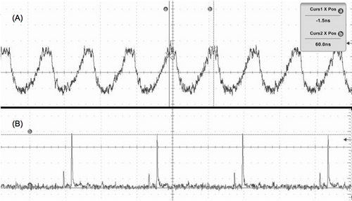
| + | We found that a 25db attenuator was required between the output fiber and the photodetector to avoid over-saturation of the detector. Without such an attenuator a sinusoidal detection signal was observed (A). This revealed 500ps FWHM bandwidth limited pulses for a 2.0Ghz bandwidth oscilloscope as shown in (B): | ||
| + | |||
| + | [[File:Sinsoidal_vs._Bandwidth_Limited.png|500px]] | ||
| + | |||
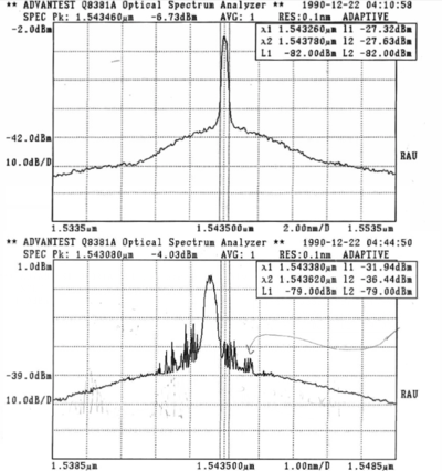
| + | Using an an Advantest Q8381A Optical Spectrum Analyzer, the optical spectrum was characterized. The top spectrum shown below reveals a stable stretched pulse for passive length 5.219 m and active: 3.095 m. Adding 0.49 m of passive fiber between the output coupler and the fiber bench, introduced side peaks on either side of the central peak. These side peaks appeared stable and may indicate the onset of a soliton pulse regime. It is also possible that they appear due to amplified competing ring modes. The FWHM for these pulses ranged from 0.5nm to 2 nm. The larger plateau that the pulses sit on is likely due to amplified spontaneous emission. | ||
| + | |||
| + | [[File:OSA_Images2.png|400px]] | ||
| + | |||
| + | |||
| + | == Other References == | ||
| + | 1. R. Paschotta, “Passive Fiber Optics,” RP Photonics Consulting GmbH (2015). | ||
| + | |||
| + | 2. E. Garmire and A. Yariv, “Correction to "Laser mode-locking with saturable absorbers",” IEEE Journal of Quantum Electronics 3, 377–377 (1967). | ||
| + | |||
| + | 3. B. Collings, K. Bergman, S. Cundiff, S. Tsuda, J. Kutz, J. Cunningham, W. Jan, M. Koch, and W. Knox, “Short cavity erbium/ytterbium fiber lasers mode-locked with a saturable Bragg reflector,” IEEE Journal of Selected Topics in Quantum Electronics 3, 1065–1075 (1997). | ||
| + | |||
| + | 4. H. Zhang, D. Tang, M. Tlidi, L. Zhao, and X. Wu, “Dispersion-managed dark solitons in erbium-doped fiber lasers,” p. 18 (2010). | ||
| + | |||
| + | 5. K. Tamura, C. R. Doerr, L. E. Nelson, H. A. Haus, and E. P. Ippen,“Technique for obtaining high-energy ultrashort pulses from an additive pulse mode-locked erbium-doped fiber ring laser,” Optics Letters 19, | ||
| + | 46 (1994). | ||
| + | |||
| + | 6. K. Tamura, E. P. Ippen, H. A. Haus, and L. E. Nelson, “77-fs pulse generation from a stretched-pulse mode-locked all-fiber ring laser, Optics Letters 18, 1080 (1993). | ||
| + | |||
| + | 7. G. Agrawal, Nonlinear Fiber Optics (Academic Press, 2001), 3rd ed. | ||
| + | |||
| + | 8. B. Saleh and M. Teich, Fundamentals of Photonics (John Wiley & Sons, Inc., Hoboken, NJ, 2007), 2nd ed. | ||
| + | |||
| + | 9. K. Tamura, L. E. Nelson, H. A. Haus, and E. P. Ippen, “Soliton versus | ||
| + | nonsoliton operation of fiber ring lasers,” Applied Physics Letters 64,149 (1994). | ||
| + | |||
| + | 10. J. L. Wagener, P. F. Wysocki, M. J. F. Digonnet, H. J. Shaw, and D. J. DiGiovanni, “Effects of concentration and clusters in erbium-doped fiber lasers,” Optics Letters 18, 2014 (1993). | ||
Latest revision as of 13:47, 6 September 2015
Contents
High Power Pulsed Fiber Lasers
Compared to bulk solid-state lasers, the chief advantage of fiber lasers is their outstanding heat-dissipation capability, which is due to the large ratio of surface to volume of such a long, thin gain medium. Fiber lasers and amplifiers have a very high single-pass gain and therefore low laser thresholds and can be efficiently pumped with diode lasers. Moreover, the broad gain bandwidth, the compactness, robustness and simplicity of operation make fiber lasers attractive for a host of applications. Rare-earth-doped PCFs offer several unique properties, which allow an upward scaling of the performance compared to conventional fiber lasers. Their main advantages are the very high pump core NA and an extended possible mode area of truly single-mode cores.
In the pulsed regime, nonlinear processes play a more dominant role and restrict power and energy scaling. However, rare-earth-doped fiber offer features which make them even look promising in this challenging operation regime. The high single-pass gain allows for simple amplification schemes, instead of multi-pass or regenerative amplification, and the average power scalability makes fiber based short-pulse laser systems interesting for applications which ask for high energies in combination with high repetition rates.
Mode Locking
In a simple laser, each of the longitudinal modes oscillates independently, with no fixed relationship between each other, in essence like a set of independent lasers all emitting light at slightly different frequencies. The individual phase of the light waves in each mode is not fixed, and may vary randomly due to such things as thermal changes in materials of the laser. In lasers with only a few oscillating modes, interference between the modes can cause beating effects in the laser output, leading to fluctuations in intensity; in lasers with many thousands of modes, these interference effects tend to average to a near-constant output intensity.
If instead of oscillating independently, each mode operates with a fixed phase between it and the other modes, the laser output behaves quite differently. Instead of a random or constant output intensity, the modes of the laser will periodically all constructively interfere with one another, producing an intense burst or pulse of light. Such a laser is said to be 'mode-locked' or 'phase-locked'. These pulses occur separated in time by τ = 2L/c, where τ is the time taken for the light to make exactly one round trip of the laser cavity. This time corresponds to a frequency exactly equal to the mode spacing of the laser, Δν = 1/τ.
The duration of each pulse of light is determined by the number of modes which are oscillating in phase (in a real laser, it is not necessarily true that all of the laser's modes will be phase-locked). If there are N modes locked with a frequency separation Δν, the overall mode-locked bandwidth is NΔν, and the wider this bandwidth, the shorter the pulse duration from the laser.
Passive Mode Locking
Passive mode-locking techniques are those that do not require a signal external to the laser (such as the driving signal of a modulator) to produce pulses. Rather, they use the light in the cavity to cause a change in some intracavity element, which will then itself produce a change in the intracavity light. A commonly used device to achieve this is a saturable absorber.
A saturable absorber is an optical device that exhibits an intensity-dependent transmission. What this means is that the device behaves differently depending on the intensity of the light passing through it. For passive mode-locking, ideally a saturable absorber will selectively absorb low-intensity light, and transmit light which is of sufficiently high intensity. When placed in a laser cavity, a saturable absorber will attenuate low-intensity constant wave light (pulse wings). However, because of the somewhat random intensity fluctuations experienced by an un-mode-locked laser, any random, intense spike will be transmitted preferentially by the saturable absorber. As the light in the cavity oscillates, this process repeats, leading to the selective amplification of the high-intensity spikes, and the absorption of the low-intensity light. After many round trips, this leads to a train of pulses and mode-locking of the laser.
Additive-pulse Mode Locking
The principle of active mode locking by modulating the resonator losses (AM mode locking) is easy to understand. A pulse with the “correct” timing can pass the modulator at times where the losses are at a minimum. Still, the wings of the pulse experience a little attenuation, which effectively leads to (slight) pulse shortening in each round trip, until this pulse shortening is offset by other effects (e.g. gain narrowing) which tend to broaden the pulse.
For stable operation, the round-trip time of the resonator must fairly precisely match the period of the modulator signal (or some integer multiple of it), so that a circulating pulse can always pass the modulator at a time with minimum losses. Even a small frequency mismatch between the laser resonator and the drive signal can lead to a strong timing jitter or even to chaotic behavior.
Synchronization between the modulator driver and the laser can be achieved either by careful adjustment of a stable laser setup, or by means of a feedback circuit which automatically adjusts either the modulation frequency or the length of the laser resonator.
The principle used in our fiber laser mode locking are:
- Nonlinear phase shifts in a single-mode fiber proportional to the intensity of the signal.
- Pulses returning from the fiber resonator into the main laser resonator interfere with those pulses which already are in the main resonator.
- Constructive interference near the peak of the pulses, but not in the wings, because the latter have acquired different nonlinear phase shifts in the fiber.
- Peak of the circulating pulse is enhanced, whereas the wings are attenuated.
Kerr Mode Locking
This is a passive mode-locking scheme in which nonlinear optical effects in intracavity components are used to provide a method of selectively amplifying high-intensity light in the cavity, and attenuation of low-intensity light.
This uses a nonlinear optical process, the optical Kerr effect, which results in high-intensity light being focussed differently from low-intensity light. By careful arrangement of optics in the laser cavity, this effect can be exploited to produce the equivalent of an ultra-fast response time saturable absorber.
Nonlinear polarization is generated in the medium, which modifies the propagation properties of the light.
- half wave plate rotates polarization so that the fast axis (highest intensity)is in line with the polarizer;
- the signal passes through polarizer with the narrowing of the pulse due to extinguishing of the low-intensity tail-modes;
- the quarter wave plate turns linearly polarized light into elliptically polarized light so that the non-linear rotation continues:
Optical bench showing half wave plate, polarizer, and quarter wave plate; another quarter wave plate has been inserted between half wave plate and polarizer to optimize the maximum intensity signal throughput:
Non-Linear Effects and Dispersion
Two effects play a role in the shaping of pulses in cavity. The first, group velocity dispersion (GVD) is a material property where higher frequency components of the pulse travel slower than lower frequency components for positive, normal dispersion, as seen in the Er-Yb doped fiber. The dispersion for such co-doped fibers has not seen considerable mention in publications, besides one study that claims a value of 0.012 ps^2/m [3]. Many publications reporting on Er doped fibers quote dispersion values between 0.040 ps^2/m [4] and 0.075ps^2/m [5]. Our study starts with a more conservative estimate for the co-doped double-clad fiber of $0.031 ps^2/m. Negative, anomalous dispersion occurs in passive fibers where core is greater than 1.3 micrometers [1]. The Corning SMF-28 fiber used in this investigation has a core of 1.5 micrometers with a widely published GVD around -0.021 ps^2/m [3], [4], [5], [6].
While material GVD introduces spectral compression and expansion as the pulse travels through the normal and anomalous dispersion fibers, an intensity dependent nonlinear phase shift also contributes to pulse shaping via the Kerr effect. With time dependent intensity, a pulse will experience a time and intensity dependent refractive index, n_NL, governed by
where n_0 is the material index of a medium, and n_2 is the nonlinear index coefficient and I is the pulse intensity [7]. With the pulse traveling with elliptical polarization through the cavity, this effect causes the vertical and horizontal polarization components to experience different phase shifts. This effect functions like material birefringence which causes a similar differential group delay, resulting in polarization mode dispersion and a rotation of the elliptical polarization which increases linearly with the length of the fiber [8]. As such, the half-wave plate is appropriately rotated to align the rotated ellipse to the polarizing element that functionally trims the pulse. The Kerr nonlinearity additionally causes self-phase modulation (SPM), which causes spectral broadening in anomalous fibers and balances spectral compression due to negative GVD. In normal dispersion fibers, like the co-doped active fiber used in our cavity, SPM functions independently of GVD [3]. The magnitude of SPM increases with length of propagation, and left unbalanced it can cause spectral oscillations and instability.
Pulse Regimes
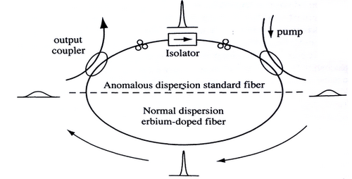
When ratio of passive to active fiber in cavity yields net zero or negative dispersion, a soliton pulse will form. Solitons are self stabilizing and maintain their spectral and temporal shape throughout the entire cavity due to the balance of GVD and SPM in the passive fiber. Solitons are commonly achieved when the length of the passive fiber is larger than that of the active to avoid significant nonlinearity [9]. Even with their inherent stability, a soliton is limited by the loss of intensity to pulse sidebands. When the temporal shape of a soliton is compressed, the pulse loses intensity to the sidebands. This is undesirable when constructing a pulsed laser for high peak power and minimal duration [9]. For a net positive dispersion in the cavity, the sideband behavior disappears and a stretched pulse regime takes place. Due to a large imbalance in GVD and SPM, the pulse undergoes spectral stretching and compression while traveling around the cavity. An output coupler can be strategically placed into the cavity in a location where the pulse is spectrally wide for optimal pulse duration. This pulse regime suffers instability, but unlike solitons, short pulse durations on the scale of hundreds of femtoseconds can be achieved without sacrificing pulse intensity [10]. At the start of this project, it was unknown whether the apparatus would produce stretched or soliton pulses. Guided by past publications reporting on stretched and soliton pulse regimes, as well as GVD values, the lengths of active and passive fiber are adjusted to observe the pulse regime with an optical spectrum analyzer. By finding the length for which the regimes switch, it is possible to experimentally determine the approximate GVD for our co-doped multi-mode active fiber.
Q-Switching by Ion Clustering
Adjusting the oscilloscope temporal resolution to 500ns/div, a much larger amplitude, lower frequency sinusoidal oscillation in the pulse train was observed. The rep rate of these giant pulses varied with pump power between hundreds of nanoseconds to tens of microseconds. This behavior is indicative of Q-switching, wherein the loss per round trip of the resonator, the resonator quality, periodically changes to induce pulsing. It is common for fibers to be doped with large concentrations of rare-earth ions to maximize gain, however this can result in ion clustering in the material lattice. If too closely spaced, two excited ions can exchange energy on the period of microseconds, called cross relaxation, causing one ion to non-radiatively decay to the ground state. Furthermore, with insufficient pump power, it may not be possible to maintain optimal population inversion. This results in an increased probability of stimulated absorption of photons already in the cavity, causing periodic gain reduction and giant pulsing. With sufficient pump power, the conversion efficiency due to cross relaxation is minimized. [10]. As the pump power is absorbed by the active fiber, the remaining pump power falls exponentially with increased active length. Considering this probable source of Q-switching, it is necessary to reduce the length of active fiber to ensure that all dopants are sufficiently pumped. By reducing the length by 18%, 0.91m, the giant pulsing was eliminated for full pump power.
Clustered versus non-clustered ion diagram:
Simulated Q-switching of mode-locked pulse train:
Data
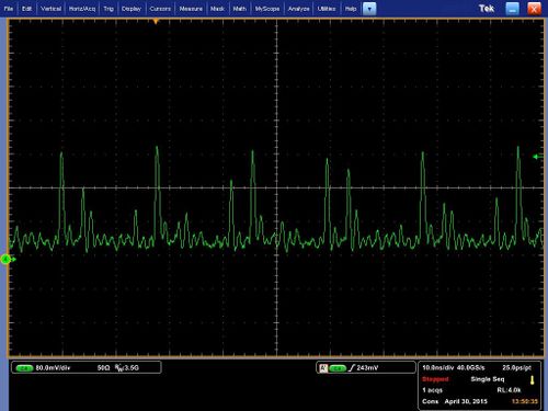
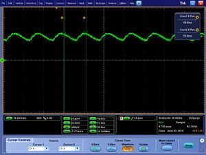
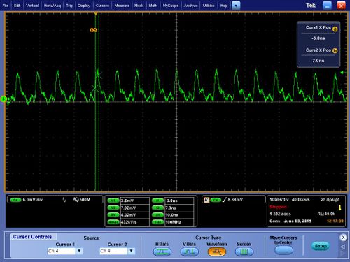
Some initial data: pulses occur one per every round trip time (based on length of all fiber elements), measurement of width of pulses is limited by detector resolution. The noise occurring due to imperfect mode interference is often comparable to the main pulses formed but highly unstable.
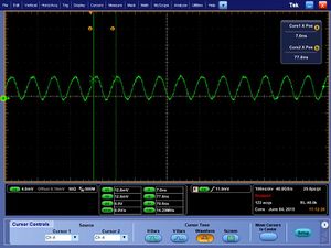
To stabilize the pulses part of the passive fiber was removed and isolator was spliced to the WDM. The pulses became more stable but not as narrow when signal is DC coupled:
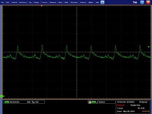
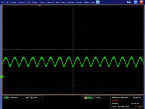
The pulses are seen to be around 10 nanoseconds in width when the signal is AC coupled:
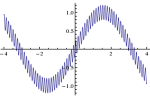
We found that a 25db attenuator was required between the output fiber and the photodetector to avoid over-saturation of the detector. Without such an attenuator a sinusoidal detection signal was observed (A). This revealed 500ps FWHM bandwidth limited pulses for a 2.0Ghz bandwidth oscilloscope as shown in (B):
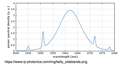
Using an an Advantest Q8381A Optical Spectrum Analyzer, the optical spectrum was characterized. The top spectrum shown below reveals a stable stretched pulse for passive length 5.219 m and active: 3.095 m. Adding 0.49 m of passive fiber between the output coupler and the fiber bench, introduced side peaks on either side of the central peak. These side peaks appeared stable and may indicate the onset of a soliton pulse regime. It is also possible that they appear due to amplified competing ring modes. The FWHM for these pulses ranged from 0.5nm to 2 nm. The larger plateau that the pulses sit on is likely due to amplified spontaneous emission.
Other References
1. R. Paschotta, “Passive Fiber Optics,” RP Photonics Consulting GmbH (2015).
2. E. Garmire and A. Yariv, “Correction to "Laser mode-locking with saturable absorbers",” IEEE Journal of Quantum Electronics 3, 377–377 (1967).
3. B. Collings, K. Bergman, S. Cundiff, S. Tsuda, J. Kutz, J. Cunningham, W. Jan, M. Koch, and W. Knox, “Short cavity erbium/ytterbium fiber lasers mode-locked with a saturable Bragg reflector,” IEEE Journal of Selected Topics in Quantum Electronics 3, 1065–1075 (1997).
4. H. Zhang, D. Tang, M. Tlidi, L. Zhao, and X. Wu, “Dispersion-managed dark solitons in erbium-doped fiber lasers,” p. 18 (2010).
5. K. Tamura, C. R. Doerr, L. E. Nelson, H. A. Haus, and E. P. Ippen,“Technique for obtaining high-energy ultrashort pulses from an additive pulse mode-locked erbium-doped fiber ring laser,” Optics Letters 19, 46 (1994).
6. K. Tamura, E. P. Ippen, H. A. Haus, and L. E. Nelson, “77-fs pulse generation from a stretched-pulse mode-locked all-fiber ring laser, Optics Letters 18, 1080 (1993).
7. G. Agrawal, Nonlinear Fiber Optics (Academic Press, 2001), 3rd ed.
8. B. Saleh and M. Teich, Fundamentals of Photonics (John Wiley & Sons, Inc., Hoboken, NJ, 2007), 2nd ed.
9. K. Tamura, L. E. Nelson, H. A. Haus, and E. P. Ippen, “Soliton versus nonsoliton operation of fiber ring lasers,” Applied Physics Letters 64,149 (1994).
10. J. L. Wagener, P. F. Wysocki, M. J. F. Digonnet, H. J. Shaw, and D. J. DiGiovanni, “Effects of concentration and clusters in erbium-doped fiber lasers,” Optics Letters 18, 2014 (1993).
