Difference between revisions of "High-Power Pulsed Fiber Laser"
m (file name correction and minor formatting changes) |
|||
| (27 intermediate revisions by the same user not shown) | |||
| Line 1: | Line 1: | ||
| − | Background: | + | = HPPFL: Gerald Buxton, Jacob Megors, Nick Kouri, and David Raschko = |
| + | |||
| + | == Spring == | ||
| + | Gerald Buxton and Jacob Megors | ||
| + | === Background:=== | ||
| + | |||
In fiber lasers, the active gain medium is an optical fiber that is doped with a rare earth element. In our laser, this element is erbium. However, other elements such as ytterbium, dysprosium, and thulium can be used. The development of fiber lasers has proved an influential component in terms of both advancement and application. For example, fiber as an optical path allows for a durable, transportable, and convenient physical apparatus. In addition, fiber properties allow for a high optical quality, while also making it easy to couple light. They allow us to achieve much greater power than otherwise, up to thousands of kW. | In fiber lasers, the active gain medium is an optical fiber that is doped with a rare earth element. In our laser, this element is erbium. However, other elements such as ytterbium, dysprosium, and thulium can be used. The development of fiber lasers has proved an influential component in terms of both advancement and application. For example, fiber as an optical path allows for a durable, transportable, and convenient physical apparatus. In addition, fiber properties allow for a high optical quality, while also making it easy to couple light. They allow us to achieve much greater power than otherwise, up to thousands of kW. | ||
| Line 10: | Line 15: | ||
In general, fiber lasers utilize stimulated emission in order to amplify light, in keeping with the famous LASER acronym (Light Amplification by Stimulated Emission of Radiation). In the process of pumping, the erbium dopant absorbs incident photons and is excited to a higher energy state. Quickly, the erbium is then relaxed to the first excited energy state. In this process, energy is stored and used to amplify the pump signal. For our three level model, the erbium occupies the ground state after each stimulated emission event. | In general, fiber lasers utilize stimulated emission in order to amplify light, in keeping with the famous LASER acronym (Light Amplification by Stimulated Emission of Radiation). In the process of pumping, the erbium dopant absorbs incident photons and is excited to a higher energy state. Quickly, the erbium is then relaxed to the first excited energy state. In this process, energy is stored and used to amplify the pump signal. For our three level model, the erbium occupies the ground state after each stimulated emission event. | ||
| − | While many fiber lasers utilize a Fabry-Perot cavity, | + | While many fiber lasers utilize a Fabry-Perot cavity, ours employs a ring cavity. One advantage of this is that most of the cavity is in fiber. |
| − | Our Set Up: | + | === Our Set Up: === |
| − | [[File:Setup.png]] | + | [[File:Setup.png|600px]] |
| − | Optical Bench Alignment: | + | === Optical Bench Alignment: === |
| Line 30: | Line 35: | ||
| − | Plot 1 | + | [[File:Bench_Loss_(dB).png|500px|left|Plot 1]] [[File:Bench_Loss.png|500px|center|Plot 2]] |
| − | |||
| + | === Address of Goals and Progress: === | ||
| − | |||
| − | + | This term, our goals were thought out with summer 2014 in mind. As participants in the Internship program, Jacob and I were grateful for the opportunity to work on our HPPFL before the summer begins. Obviously, our summer will be busy and quick, so we prepared our goals with this in mind. | |
| + | |||
| + | First, we wanted to measure and optimize the loss through the fiber bench in our set up. For more on this, please refer to the wiki page that specifically details our process, progress, and results. We were thrilled with our results in this area. Importantly, we were able to get hands-on experience with new materials and devices. For example, the Thorlabs IR Beam Profiler helped us confront this goal, while giving us a great excuse to learn new software and skills. | ||
| + | Secondly, we hoped to reproduce the self-pulsing behavior that Dar and David observed over the summer. With our new and improved bench (~80% efficiency, no elements), we were quickly able to reproduce these results. In addition, we developed a plan to overcome the presumed culprits of self-pulsing. Basically, it has been shown that lasers with erbium-doped fibers often display symptoms of self-pulsing operation. For more on the theory behind this, please refer to the (Insert graphs from an illustrator program that we discussed) appropriate section. To overcome this phenomenon, we hope that by adding a second 980 pump we will have enough power to overcome the problem. | ||
| − | + | Next, we hoped to develop a method of fusion splicing EDF-80 to SMF-28 to replace the connectorized parts of the cavity. Previously, the laser had seen evidence of back reflections, hopefully due simply to faulty and imperfect connections. With this goal, we hoped to achieve a few things both practical and educational. Firstly, we hoped to better familiarize ourselves with the process of fusion splicing, one that is extremely relevant in industrial settings. In addition, we hoped to develop a consistent method for confronting the problem of EDF to SMF fusion splices. For whatever reason, the LID (Light-Injection Detection) system failed to function properly for this particular splice. As a result, we were unable to know with great certainty how efficient each splice was. We designed a simple factorial design experiment that would allow us to rather simply deduce the correct parameters for a good splice. There were many problems on the way. We hoped to test a series of values for specific parameters (variable on the RXS77), and then characterize the loss. To characterize the loss, we would essentially shine an alignment laser of known power through our spliced fiber, and measure the resultant loss through the connection. These results would be of great value for the lab, as this splice would no longer be an issue of great and unknown concern. We battled many obstacles along the way, but we eventually settled on both procedure and design. We have a new alignment laser that will not be absorbed through EDF. In addition, we were attempting to fusion splice fiber that had non-matching core sizes. We have ordered new fiber and corrected this problem. We are in great shape with respect to this goal, and we were able to perform a preliminary fractional factorial design experiment. While the results were not sufficient to deliver a conclusive answer, the experiment was worthwhile. We tested 4 parameters: Autofeed, prefusion time, fusion time, and fusion current. The results are documented below. The table provides the loss measurements for a given splice with the specified parameters. | |
| + | The first file below shows the results of the ANOVA we ran. As you can see, the only parameter with a P-Value of less than 0.5 is autofeed. A p-value of 0.5 disproves the null hypothesis for the experiment. In our case, the null hypothesis is that these variables do not effect the quality of the fusion splice. | ||
| − | + | [[File:ANOVA.png|500px]] | |
| − | + | [[File:Splices3.png]] | |
| + | [[File:Cell_Means.png|500px]] | ||
| − | + | File 4 shows that we did not see a time series. This is a good thing, and it basically means that there was nothing systematically wrong with our procedure. | |
| − | + | [[File:Timeseries.png|500px]] | |
| − | |||
[[File:Boxplot.png]] | [[File:Boxplot.png]] | ||
| − | [[File: | + | |
| + | |||
| + | |||
| + | When we had the laser up and running, we were seeing self-pulsing. | ||
| + | |||
| + | [[File:140613_113215.png]] | ||
| + | |||
| + | |||
| + | To overcome this, we attempted to simply add a second pump to blast through the self-pulsing. We used a polarization combiner in order to do this. However, we were not able to eliminate the self pulsing. This will be something we confront in the summer. | ||
Finally, we hoped to be able to measure the dispersion of pumped EDF-80. In any final and functional laser, these measurements will be vital for deterring the correct length of EDF to be used. We will not get there this term, but we hope to be in a position to achieve these measurements this summer. | Finally, we hoped to be able to measure the dispersion of pumped EDF-80. In any final and functional laser, these measurements will be vital for deterring the correct length of EDF to be used. We will not get there this term, but we hope to be in a position to achieve these measurements this summer. | ||
| + | |||
| + | |||
| + | == Summer Optimization: == | ||
| + | Nick Kouri and David Raschko | ||
| + | |||
| + | === Goals: === | ||
| + | |||
| + | As we take over the project for Jacub and Gerald, we have several goals in place we wish to accomplish. They are namely: | ||
| + | |||
| + | 1. Resolve the Q-Switching problem and achieve Mode-Locke pulses. | ||
| + | |||
| + | 2. Optimize the power such that there’s enough average power for an autocorrelator (at least 50mW). | ||
| + | |||
| + | 2B. Create a Power characterization chart when optimized. | ||
| + | |||
| + | 3. Replace connectors with Fusion Splices. | ||
| + | |||
| + | 4. Replace ER-80 with ER-30 | ||
| + | |||
| + | 5. Determine beam characteristics of the pulse | ||
| + | |||
| + | 6. Determine the pulse width and by extension peak power. | ||
| + | |||
| + | Each goal was tackled individually, and each goal was met with the exception of goal 6 which had to be approximated. Goal 4 ended up solving goal 1, and goal 3 enhanced the efficiency enough for goal 2. Goals 5 and 6 were tackled separately. Goal 2B was done last (though it related so heavily to goal 2 it can be considered a subsection) to produce a chart where the output power could be determined at any input pump current. | ||
| + | |||
| + | |||
| + | === Setup: === | ||
| + | |||
| + | The setup used by Jacub and Gerald changed very little from Spring to summer. Figure 1 below shows the current setup, and as can be seen the major difference is the removal of connectors and the addition of the fiber coupler. The coupler was included as to allow the maximum light from the pumps into the ring while still providing a means to determine how much pump is being generated. | ||
| + | |||
| + | |||
| + | [[File:HPPFLS.JPG]] | ||
| + | |||
| + | Figure 1 | ||
| + | |||
| + | The ER-80 was replaced with approximately 2 meters of ER-30 to reduce the likelihood of ion clustering and potentially remove the Q-switching. In this regard it was successful. By simply replacing the ER-80 with ER-30, the Q-switching stopped, and very noisy mode-locked pulses could be observed. We believed the noise was due to back reflections off the connectors. We also believed the connectors were causing power losses, so we removed all of them (other than the one directly at the second pump) and replaced them with fusion splices. We used the program developed by Jacub and Gerald for the SMF to ER-30 splice and it worked much better than the connectors. | ||
| + | |||
| + | With every connector removed, the output power at 0.67 amps on each pump became 117 mW (or 120 mW at 0.7 A each). This was more than enough to run the autocorrelator. Yet before we had access to the autocorrelator, we used a pair of fast photodiodes to determine the repetition rate of the laser. When using the slowest detector we got the waveform below in Figure 2. | ||
| + | |||
| + | [[File:slow_detector.JPG]] | ||
| + | |||
| + | Figure 2 | ||
| + | |||
| + | This waveform had pulses every 14.4 ns, but the pulse width itself was so large due to the bandwidth limit of the detector. So once a faster detector was acquired, we hooked it up and saw the image in Figure 3 below | ||
| + | |||
| + | [[File:fast_detector.JPG]] | ||
| + | |||
| + | Figure 3 | ||
| + | |||
| + | This image also has a repetition rate of 14.4 ns from large peak to large peak, which made us confident in an actual repetition rate of 14.4 ns. Its pulses were measured at 460ps, which was also the bandwidth of the fast detector. Since we were right at the bandwidth of the detector, we felt it was safe to assume the actual pulses were considerably faster. In order to determine exactly how fast, we would need an autocorrelator. | ||
| + | |||
| + | |||
| + | |||
| + | === Autocorrelator: === | ||
| + | |||
| + | In order to hook up the Minioptic Technology Miniscan Autocorrelator, a set of coupling mirrors were needed. Figure 5 below shows the output coupler used to align the autocorrelator (and the M_2 tool used later). | ||
| + | |||
| + | [[File:Autocorrelator.JPG]] | ||
| + | |||
| + | [[File:Output_Coupler.JPG]] | ||
| + | |||
| + | |||
| + | Figure 5 | ||
| + | |||
| + | |||
| + | Once perfectly aligned into the autocorrelator the beam traveled along the path shown in Figure 4. The beam enters through iris 1, passes through hole 1 where it is split by a beamsplitter. From there forward the device acts as a Michelson interferometer. The path length difference of the arms is the space between the beamsplitter and the first mirror. The rotation delay line is a set of mirrors that spin at a known speed (5 Hz) such that when they align perfectly (back through the beamsplitter to hole 2) an interference pattern of formed at mirror 8. The tilt and position of the autocorrelator can then be adjusted such that the zero order fringe is centered on the mirror. This mirror is a focusing mirror such it focusing the on the non-linear crystal. The crystal then performs SHG which is sent through a filter to remove the first harmonic. The remaining second harmonic then appears on the detector. The more power is provided to the crystal, the more SHG is produced. | ||
| + | |||
| + | |||
| + | According to the Autocorrelator, the output signal on the detector should appear like Figure 6. The first step represents the a DC offset in the detector, the second step is remnants of first harmonic getting through, and the peak on top is the second harmonic generation. To calculate the pulse width of the laser, the width of the second harmonic is put over the space between pulses (200 ms) and multiplied by 360 (degrees), a constant K (3.80 ps/degree) and a Gaussian coefficient 0.707. When we ran the signal through the system we got the signal below in Figure 6. | ||
| + | |||
| + | [[File:ifsignal.JPG]] | ||
| + | |||
| + | Figure 6 | ||
| + | |||
| + | When the signal was removed, the small hump on the left dropped to be level with the flat plateau. We understood the plateau to be the first step and the hump to be the first harmonic. However, we were not able to find any SHG in the signal. We think this may have been due to the filter not removing enough of the first harmonic. This would drown the small second harmonic signal and make it undetectable. Misalignment could be another source of the lack of SHG. | ||
| + | |||
| + | However, we were able to shrink our previous estimate of 460ps down to 36ps peak. This new value was determined by taking the full width half max of the first harmonic and determining the actual pulse width of that. Since the second harmonic would be a small signal riding on the larger width first harmonic, it seems reasonable to say that the second harmonic pulses would have to be at least as narrow as the first harmonic wave it is riding on. | ||
| + | |||
| + | === Beam Profiler: === | ||
| + | |||
| + | After determining that the autocorrelator would not yield the result we wanted, we decided to move on to the beam characterization using a Thorlabs BP209-IR and a translation stage for use as an M_2 tool. The same two mirror setup used with the autocorrelator was used to align the beam profiler. Before the system was safe to run through a beam profiler, an accurate measure of output power vs drive current had to be determined to ensure it would be known exactly how much power would be sent into the profiler. Figure 7 below shows the determined output power vs drive current curve. | ||
| + | |||
| + | |||
| + | [[File:Power_Curve.JPG]] | ||
| + | |||
| + | Figure 7 | ||
| + | |||
| + | Once we had the curve in Figure 7, we drove the laser with as little current as we could to ensure the beam profiler wouldn't be saturated. According to the maunual, the profiler ould handle up to a watt of of average power, but we drove it at 50mW. Figure 8 below shows the output laser before being put through a lens. | ||
| + | |||
| + | [[File:3d_Profile.jpg]] | ||
| + | |||
| + | Figure 8 | ||
| + | |||
| + | A 200mm lens was then placed in front of the beam profiler and an M_2 measurement was taken. Figure 9 below shows the results of the M_2 test. | ||
| + | |||
| + | [[File:M_2.JPG]] | ||
| + | |||
| + | Figure 9 | ||
| + | |||
| + | This test shows we have a Gaussian beam with an M_2 of approximately 1, with a beam diameter of 3.701 mm. These characterizations can be very useful to any group who takes over the project, for the smaller the beam waist, the higher the power per unit area. Adding a condensing lens system would be a great way to increase the Irradiance. | ||
| + | |||
| + | The good news from this test is that we can be sure that our beam is indeed Gaussian, meaning we were justified in using the Gaussian coefficient in our pulse width calculation. | ||
| + | |||
| + | |||
| + | === Final Results: === | ||
| + | |||
| + | The summer’s results are all summarized below: | ||
| + | |||
| + | 1. Beam Type: Gaussian | ||
| + | |||
| + | 2. M_2: 0.98 | ||
| + | |||
| + | 3. Beam Diameter: 3.701 mm | ||
| + | |||
| + | 4. Repetition Rate: 14.4 ns | ||
| + | |||
| + | 5. Average Power: 120 mW | ||
| + | |||
| + | 6. Pulse Width*: 36.75 ps | ||
| + | |||
| + | 7. Peak Power: 47.02 W | ||
| + | |||
| + | **The pulse width is the finest width that could be determined while using the autocorrelator, but is in fact not the actual pulse width which we believe to be in the femtosecond range. | ||
| + | |||
| + | |||
| + | === Moving Forward: === | ||
| + | |||
| + | For any group wishing to take over this project, we have a few suggestions on how to quickly bring the system back to optimal as well as where to focus. To get the system optimized, the polarization controllers need to be adjusted and the power needs to be watched. Using a free space power meter at either the output or the 1% tap of the fiber coupler, the polarization controllers can be slowly adjusted to maximize power to the output. If both pumps are on at 0.67 A, then the output power should be 117mW when optimized. | ||
| + | |||
| + | If any fusion splices need to be redone, we recommend taping them to a flat post bolted to the table to keep them from moving. | ||
| + | |||
| + | As for ideas for where to focus, if you can secure the Miniscan Autocorrelator (or any autocorrelator), then it would be well worth the time to get t perfect such that SHG can be picked up. It may be worthwhile to use an autocorrelator system that has the SHG travel a different trajectory than the first harmonic, such that the filter isn't necessary. | ||
| + | |||
| + | Another idea would be to determine the beam dispersion characteristics at the output and find ways to minimize that. One could also imagine using the RP Fiber Power software to determine the optimal length of fiber to maximize power (or get the data from the Fiber Dispersion lab group). The final area to tackle would be converting the system to an easily transportable size. | ||
Latest revision as of 20:19, 24 August 2014
HPPFL: Gerald Buxton, Jacob Megors, Nick Kouri, and David Raschko
Spring
Gerald Buxton and Jacob Megors
Background:
In fiber lasers, the active gain medium is an optical fiber that is doped with a rare earth element. In our laser, this element is erbium. However, other elements such as ytterbium, dysprosium, and thulium can be used. The development of fiber lasers has proved an influential component in terms of both advancement and application. For example, fiber as an optical path allows for a durable, transportable, and convenient physical apparatus. In addition, fiber properties allow for a high optical quality, while also making it easy to couple light. They allow us to achieve much greater power than otherwise, up to thousands of kW.
So how does a fiber laser work? Well, fiber amplifiers form the basis of all conceptual understanding. Basically, a typical fiber laser consists of a fiber amplifier placed within a cavity. The cavity, or ring, in our case, serves the purpose of providing the necessary optical feedback. The pumping process drives the activity of the laser, while there are several ways that this can work. For ours, and basically all erbium doped fiber lasers, the pumping scheme is considered to be “three level.”
In general, fiber lasers utilize stimulated emission in order to amplify light, in keeping with the famous LASER acronym (Light Amplification by Stimulated Emission of Radiation). In the process of pumping, the erbium dopant absorbs incident photons and is excited to a higher energy state. Quickly, the erbium is then relaxed to the first excited energy state. In this process, energy is stored and used to amplify the pump signal. For our three level model, the erbium occupies the ground state after each stimulated emission event.
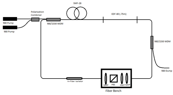
While many fiber lasers utilize a Fabry-Perot cavity, ours employs a ring cavity. One advantage of this is that most of the cavity is in fiber.
Our Set Up:
Optical Bench Alignment:
Early on, aligning the optical bench was a huge area of focus for our group. The bench was in bad shape, and we quickly realized realignment was necessary. Dar and David were able to achieve a fifty percent efficiency through the bench, and we kept this number in mind. In aligning the bench, it is necessary to first achieve something close to perfect collimation for fiber ports on both sides. Each fiber port has essentially 5 degrees of freedom. There are the x and y screws, which serve to tilt the lens in such a way that the direction of the beam can be variably moved up and down, and left to right. In addition, there are three “z” screws, which move the lens either closer or further from the fiber tip. In this way, you can pass the beam between divergence, collimation, and convergence.
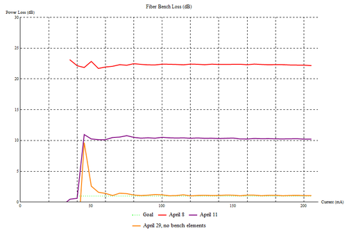
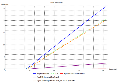
At first, we attempted to simply adjust these screws until we visually observed a collimated beam to the best of our ability. We used an IR card to determine the beam diameter along its path. While this improved the efficiency of the bench from when we found it, it was still very far away from where we needed to be. Theoretically, the bench should be able to achieve an efficiency of around eighty percent. Below, Plot 1 displays the loss levels for our first alignment attempt.
Soon, we stumbled upon a method that worked. We made a video of our process, so you can follow along if you would like. First, we had to make sure that we had the alignment laser pointed straight. We placed two alignment apertures on the optical bench, one as close as it could be to the fiber port in question, and one as far away as possible. Once the output through the second aperture was maximized, we were confident we had the laser pointing in the right direction. Next, we set up a beam profiler that was along this line of light. We hypothesized that collimation could be most closely achieved by minimizing the spot at some distant point. As such, the beam profiler was placed at the furthest point it could, still in line with the alignment laser. The beam profiler was a necessity, as it would be very difficult to characterize the size of a tiny spot such as the alignment laser. We observed a minimum by using the Thorlabs Beam Profiler software, then repeated the process with our second fiber port. Now, we were ready to place each fiber port back on the bench, and use a power meter to characterize our loss. Within the bench, we were able to carefully tweak the screws to fine align the bench. We achieved a maximum efficiency of 84%, a number we were thrilled with. Plot 2 displays the loss below.
Address of Goals and Progress:
This term, our goals were thought out with summer 2014 in mind. As participants in the Internship program, Jacob and I were grateful for the opportunity to work on our HPPFL before the summer begins. Obviously, our summer will be busy and quick, so we prepared our goals with this in mind.
First, we wanted to measure and optimize the loss through the fiber bench in our set up. For more on this, please refer to the wiki page that specifically details our process, progress, and results. We were thrilled with our results in this area. Importantly, we were able to get hands-on experience with new materials and devices. For example, the Thorlabs IR Beam Profiler helped us confront this goal, while giving us a great excuse to learn new software and skills.
Secondly, we hoped to reproduce the self-pulsing behavior that Dar and David observed over the summer. With our new and improved bench (~80% efficiency, no elements), we were quickly able to reproduce these results. In addition, we developed a plan to overcome the presumed culprits of self-pulsing. Basically, it has been shown that lasers with erbium-doped fibers often display symptoms of self-pulsing operation. For more on the theory behind this, please refer to the (Insert graphs from an illustrator program that we discussed) appropriate section. To overcome this phenomenon, we hope that by adding a second 980 pump we will have enough power to overcome the problem.
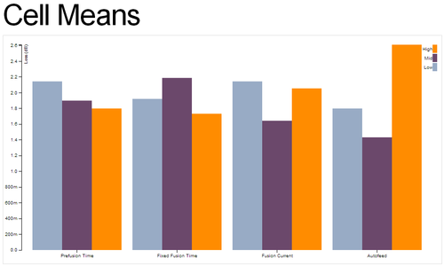
Next, we hoped to develop a method of fusion splicing EDF-80 to SMF-28 to replace the connectorized parts of the cavity. Previously, the laser had seen evidence of back reflections, hopefully due simply to faulty and imperfect connections. With this goal, we hoped to achieve a few things both practical and educational. Firstly, we hoped to better familiarize ourselves with the process of fusion splicing, one that is extremely relevant in industrial settings. In addition, we hoped to develop a consistent method for confronting the problem of EDF to SMF fusion splices. For whatever reason, the LID (Light-Injection Detection) system failed to function properly for this particular splice. As a result, we were unable to know with great certainty how efficient each splice was. We designed a simple factorial design experiment that would allow us to rather simply deduce the correct parameters for a good splice. There were many problems on the way. We hoped to test a series of values for specific parameters (variable on the RXS77), and then characterize the loss. To characterize the loss, we would essentially shine an alignment laser of known power through our spliced fiber, and measure the resultant loss through the connection. These results would be of great value for the lab, as this splice would no longer be an issue of great and unknown concern. We battled many obstacles along the way, but we eventually settled on both procedure and design. We have a new alignment laser that will not be absorbed through EDF. In addition, we were attempting to fusion splice fiber that had non-matching core sizes. We have ordered new fiber and corrected this problem. We are in great shape with respect to this goal, and we were able to perform a preliminary fractional factorial design experiment. While the results were not sufficient to deliver a conclusive answer, the experiment was worthwhile. We tested 4 parameters: Autofeed, prefusion time, fusion time, and fusion current. The results are documented below. The table provides the loss measurements for a given splice with the specified parameters.
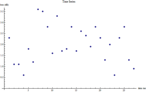
The first file below shows the results of the ANOVA we ran. As you can see, the only parameter with a P-Value of less than 0.5 is autofeed. A p-value of 0.5 disproves the null hypothesis for the experiment. In our case, the null hypothesis is that these variables do not effect the quality of the fusion splice.
File 4 shows that we did not see a time series. This is a good thing, and it basically means that there was nothing systematically wrong with our procedure.
When we had the laser up and running, we were seeing self-pulsing.
To overcome this, we attempted to simply add a second pump to blast through the self-pulsing. We used a polarization combiner in order to do this. However, we were not able to eliminate the self pulsing. This will be something we confront in the summer.
Finally, we hoped to be able to measure the dispersion of pumped EDF-80. In any final and functional laser, these measurements will be vital for deterring the correct length of EDF to be used. We will not get there this term, but we hope to be in a position to achieve these measurements this summer.
Summer Optimization:
Nick Kouri and David Raschko
Goals:
As we take over the project for Jacub and Gerald, we have several goals in place we wish to accomplish. They are namely:
1. Resolve the Q-Switching problem and achieve Mode-Locke pulses.
2. Optimize the power such that there’s enough average power for an autocorrelator (at least 50mW).
2B. Create a Power characterization chart when optimized.
3. Replace connectors with Fusion Splices.
4. Replace ER-80 with ER-30
5. Determine beam characteristics of the pulse
6. Determine the pulse width and by extension peak power.
Each goal was tackled individually, and each goal was met with the exception of goal 6 which had to be approximated. Goal 4 ended up solving goal 1, and goal 3 enhanced the efficiency enough for goal 2. Goals 5 and 6 were tackled separately. Goal 2B was done last (though it related so heavily to goal 2 it can be considered a subsection) to produce a chart where the output power could be determined at any input pump current.
Setup:
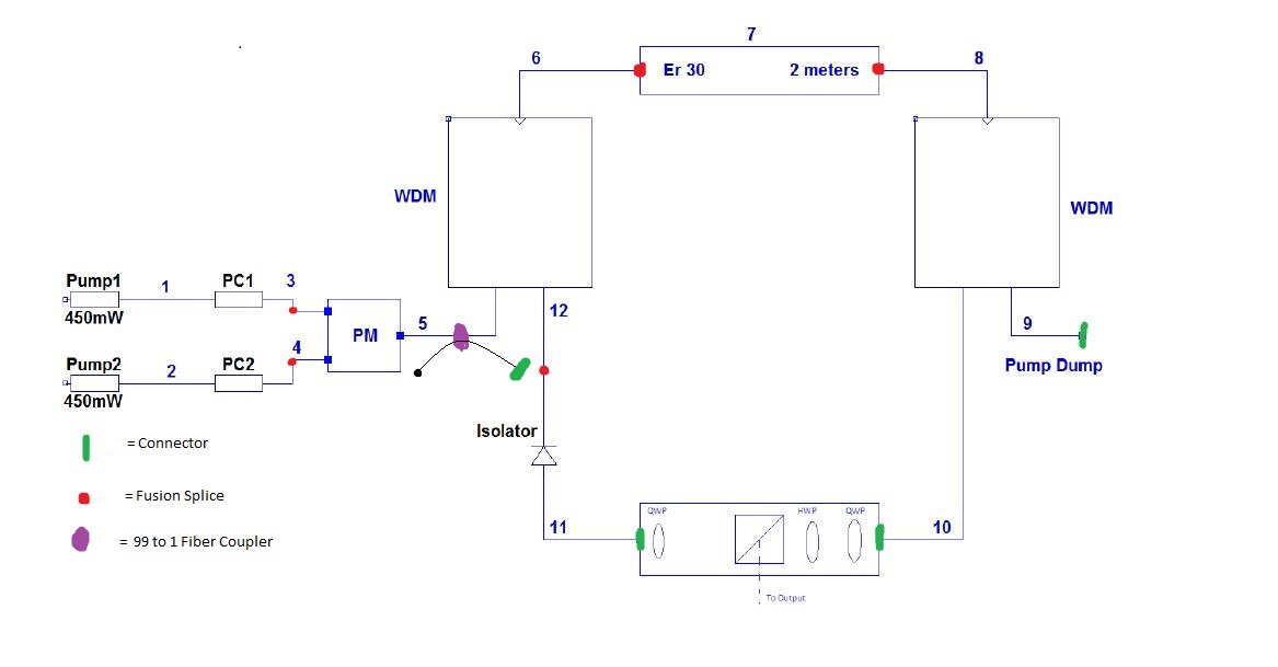
The setup used by Jacub and Gerald changed very little from Spring to summer. Figure 1 below shows the current setup, and as can be seen the major difference is the removal of connectors and the addition of the fiber coupler. The coupler was included as to allow the maximum light from the pumps into the ring while still providing a means to determine how much pump is being generated.
Figure 1
The ER-80 was replaced with approximately 2 meters of ER-30 to reduce the likelihood of ion clustering and potentially remove the Q-switching. In this regard it was successful. By simply replacing the ER-80 with ER-30, the Q-switching stopped, and very noisy mode-locked pulses could be observed. We believed the noise was due to back reflections off the connectors. We also believed the connectors were causing power losses, so we removed all of them (other than the one directly at the second pump) and replaced them with fusion splices. We used the program developed by Jacub and Gerald for the SMF to ER-30 splice and it worked much better than the connectors.
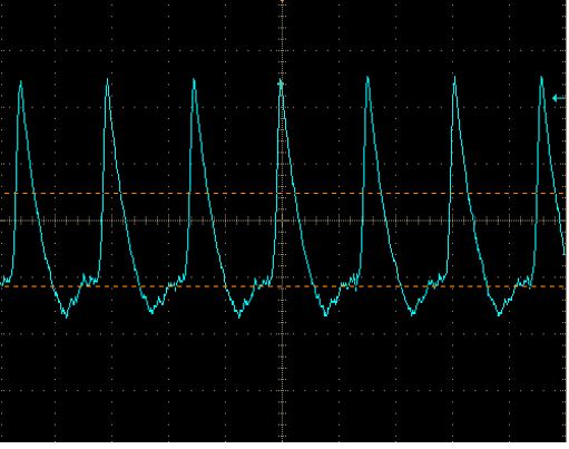
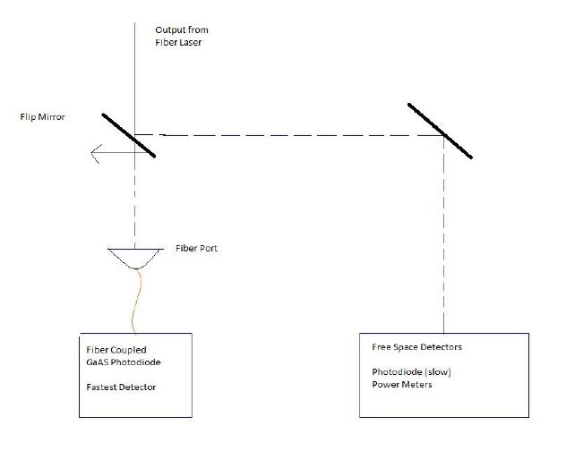
With every connector removed, the output power at 0.67 amps on each pump became 117 mW (or 120 mW at 0.7 A each). This was more than enough to run the autocorrelator. Yet before we had access to the autocorrelator, we used a pair of fast photodiodes to determine the repetition rate of the laser. When using the slowest detector we got the waveform below in Figure 2.
Figure 2
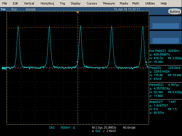
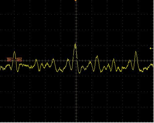
This waveform had pulses every 14.4 ns, but the pulse width itself was so large due to the bandwidth limit of the detector. So once a faster detector was acquired, we hooked it up and saw the image in Figure 3 below
Figure 3
This image also has a repetition rate of 14.4 ns from large peak to large peak, which made us confident in an actual repetition rate of 14.4 ns. Its pulses were measured at 460ps, which was also the bandwidth of the fast detector. Since we were right at the bandwidth of the detector, we felt it was safe to assume the actual pulses were considerably faster. In order to determine exactly how fast, we would need an autocorrelator.
Autocorrelator:
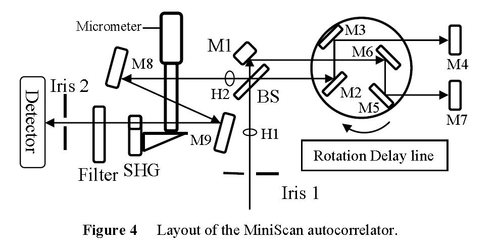
In order to hook up the Minioptic Technology Miniscan Autocorrelator, a set of coupling mirrors were needed. Figure 5 below shows the output coupler used to align the autocorrelator (and the M_2 tool used later).
Figure 5
Once perfectly aligned into the autocorrelator the beam traveled along the path shown in Figure 4. The beam enters through iris 1, passes through hole 1 where it is split by a beamsplitter. From there forward the device acts as a Michelson interferometer. The path length difference of the arms is the space between the beamsplitter and the first mirror. The rotation delay line is a set of mirrors that spin at a known speed (5 Hz) such that when they align perfectly (back through the beamsplitter to hole 2) an interference pattern of formed at mirror 8. The tilt and position of the autocorrelator can then be adjusted such that the zero order fringe is centered on the mirror. This mirror is a focusing mirror such it focusing the on the non-linear crystal. The crystal then performs SHG which is sent through a filter to remove the first harmonic. The remaining second harmonic then appears on the detector. The more power is provided to the crystal, the more SHG is produced.
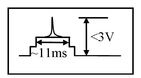
According to the Autocorrelator, the output signal on the detector should appear like Figure 6. The first step represents the a DC offset in the detector, the second step is remnants of first harmonic getting through, and the peak on top is the second harmonic generation. To calculate the pulse width of the laser, the width of the second harmonic is put over the space between pulses (200 ms) and multiplied by 360 (degrees), a constant K (3.80 ps/degree) and a Gaussian coefficient 0.707. When we ran the signal through the system we got the signal below in Figure 6.
Figure 6
When the signal was removed, the small hump on the left dropped to be level with the flat plateau. We understood the plateau to be the first step and the hump to be the first harmonic. However, we were not able to find any SHG in the signal. We think this may have been due to the filter not removing enough of the first harmonic. This would drown the small second harmonic signal and make it undetectable. Misalignment could be another source of the lack of SHG.
However, we were able to shrink our previous estimate of 460ps down to 36ps peak. This new value was determined by taking the full width half max of the first harmonic and determining the actual pulse width of that. Since the second harmonic would be a small signal riding on the larger width first harmonic, it seems reasonable to say that the second harmonic pulses would have to be at least as narrow as the first harmonic wave it is riding on.
Beam Profiler:
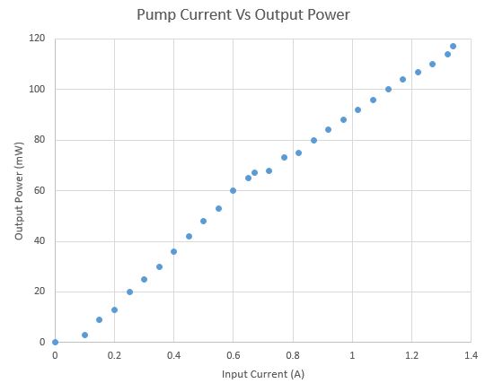
After determining that the autocorrelator would not yield the result we wanted, we decided to move on to the beam characterization using a Thorlabs BP209-IR and a translation stage for use as an M_2 tool. The same two mirror setup used with the autocorrelator was used to align the beam profiler. Before the system was safe to run through a beam profiler, an accurate measure of output power vs drive current had to be determined to ensure it would be known exactly how much power would be sent into the profiler. Figure 7 below shows the determined output power vs drive current curve.
Figure 7
Once we had the curve in Figure 7, we drove the laser with as little current as we could to ensure the beam profiler wouldn't be saturated. According to the maunual, the profiler ould handle up to a watt of of average power, but we drove it at 50mW. Figure 8 below shows the output laser before being put through a lens.
Figure 8
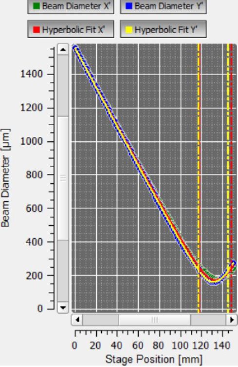
A 200mm lens was then placed in front of the beam profiler and an M_2 measurement was taken. Figure 9 below shows the results of the M_2 test.
Figure 9
This test shows we have a Gaussian beam with an M_2 of approximately 1, with a beam diameter of 3.701 mm. These characterizations can be very useful to any group who takes over the project, for the smaller the beam waist, the higher the power per unit area. Adding a condensing lens system would be a great way to increase the Irradiance.
The good news from this test is that we can be sure that our beam is indeed Gaussian, meaning we were justified in using the Gaussian coefficient in our pulse width calculation.
Final Results:
The summer’s results are all summarized below:
1. Beam Type: Gaussian
2. M_2: 0.98
3. Beam Diameter: 3.701 mm
4. Repetition Rate: 14.4 ns
5. Average Power: 120 mW
6. Pulse Width*: 36.75 ps
7. Peak Power: 47.02 W
- The pulse width is the finest width that could be determined while using the autocorrelator, but is in fact not the actual pulse width which we believe to be in the femtosecond range.
Moving Forward:
For any group wishing to take over this project, we have a few suggestions on how to quickly bring the system back to optimal as well as where to focus. To get the system optimized, the polarization controllers need to be adjusted and the power needs to be watched. Using a free space power meter at either the output or the 1% tap of the fiber coupler, the polarization controllers can be slowly adjusted to maximize power to the output. If both pumps are on at 0.67 A, then the output power should be 117mW when optimized.
If any fusion splices need to be redone, we recommend taping them to a flat post bolted to the table to keep them from moving.
As for ideas for where to focus, if you can secure the Miniscan Autocorrelator (or any autocorrelator), then it would be well worth the time to get t perfect such that SHG can be picked up. It may be worthwhile to use an autocorrelator system that has the SHG travel a different trajectory than the first harmonic, such that the filter isn't necessary.
Another idea would be to determine the beam dispersion characteristics at the output and find ways to minimize that. One could also imagine using the RP Fiber Power software to determine the optimal length of fiber to maximize power (or get the data from the Fiber Dispersion lab group). The final area to tackle would be converting the system to an easily transportable size.
