Difference between revisions of "Electronics"
| (2 intermediate revisions by the same user not shown) | |||
| Line 146: | Line 146: | ||
When the Tone Potentiometer is all the way to the bass side, The opamp has a gain of 1k/1k=1. The components R7, C5, and C6 create a low pass filter with a cutoff frequency 360Hz, which is low in the hearing range (20-20kHz). | When the Tone Potentiometer is all the way to the bass side, The opamp has a gain of 1k/1k=1. The components R7, C5, and C6 create a low pass filter with a cutoff frequency 360Hz, which is low in the hearing range (20-20kHz). | ||
When the Tone Potentiometer is all the way to the treble side, the opamp has a gain of 1+1k/Z(R8+C6), the impedance of R8 and C6. This impedance will be low for high frequencies, and high for low frequencies, resulting in a treble boost. The cutoff frequency for R8 and C6 is 3.25kHz. | When the Tone Potentiometer is all the way to the treble side, the opamp has a gain of 1+1k/Z(R8+C6), the impedance of R8 and C6. This impedance will be low for high frequencies, and high for low frequencies, resulting in a treble boost. The cutoff frequency for R8 and C6 is 3.25kHz. | ||
| + | |||
| + | |||
| + | |||
| + | |||
| Line 161: | Line 165: | ||
Now that we understand how the circuit works, lets look at the data I took with an oscilloscope. The input is a sine wave, and the voltage is set at 1V peak to peak. | Now that we understand how the circuit works, lets look at the data I took with an oscilloscope. The input is a sine wave, and the voltage is set at 1V peak to peak. | ||
| − | 100Hz | + | *100Hz Drive Pot 0% |
| − | [[File:100hz1vppdrive0.jpg|400px|left]] [[File:100hz1vppdrive100.jpg]] | + | [[File:100hz1vppdrive0.jpg|400px|left]] Drive Pot 100% [[File:100hz1vppdrive100.jpg|450px|right]] |
| + | |||
| + | |||
| + | |||
| + | |||
| + | Note the y-axis asymmetry of both waveforms. With the drive at 0%, the wave almost resembles a sine wave. The 100Hz waveform is not very heavily clipped when the drive pot is at 100% | ||
| + | |||
| + | |||
| + | |||
| + | *1kHz Tone Pot 0% | ||
| + | [[File:1khz1vpptone0.jpg|400px|left]] Tone Pot 100% [[File:1khz1vpptone100.jpg|450px|right]] | ||
| + | |||
| + | |||
| + | |||
| + | |||
| + | |||
| + | |||
| + | |||
| + | |||
| + | |||
| + | |||
| + | |||
| + | Note the y-axis asymmetry switches sides between waveforms. With the tone at 0%, the wave resembles a triangle wave. The 1kHz waveform is heavily clipped when the tone pot is at 100% | ||
| + | |||
| + | |||
| + | |||
| + | *4kHz Tone Pot 0% | ||
| + | [[File:4khz1vpptone0.jpg|400px|left]] Tone Pot 100% [[File:4khz1vpptone100.jpg|450px|right]] | ||
| + | |||
| + | |||
| + | |||
| + | |||
| + | |||
| + | |||
| + | |||
| + | |||
| + | |||
| + | |||
| + | |||
| + | With the tone at 0%, the wave resembles a triangle wave. Notice how the peak of the signal at 0% is ~.15v and the peak of signal at 100% is ~1V. The 4kHz waveform is heavily clipped when the tone pot is at 100%, and looks symmetrical on the y-axis. | ||
| + | |||
| + | |||
| + | |||
| + | |||
| + | ----Trends: Higher frequencies are more heavily clipped, and louder high frequencies have a nearly symmetric waveform. Lower frequencies are less clipped and exhibit more asymmetric behaviour. | ||
| − | + | Fourier Transform: The output waves were f+2n (n from 0 to infinity), where f is the input frequency and decayed exponentially. This is interesting, because it is not what I would expect to see. I would expect the effect to generate octave harmonics, but octaves are 2*f, not 3*f or 5*f etc. The first harmonic is a fifth (in musical terms) and the second is a major third. | |
Latest revision as of 15:48, 21 March 2014
-Electronics-
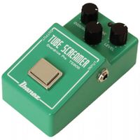
Winter 2014 For my project I am building an electric guitar analog effects pedal. The pedal is called the "Tube Screamer" and is an overdrive effect, which clips an amplified signal.
Why build a guitar pedal? I want to understand what makes overdrive sound good. Oftentimes, when people speak of "distortion", they are talking about noise that is unwanted, but with guitars, there is a good distortion, which make the guitar signal sound good. As I built the pedal, I analyzed it with an oscilloscope, as well as did research, to better understand what makes it sound qualitatively good to human ears.
Basic Guitar Physics
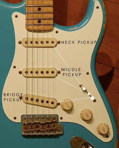
- An electric guitar works by converting sound into an alternating current, using pickups. A pickup is a magnet with wire densely coiled around it. It creates a magnetic field around the guitar string, so that when the string vibrates, there is a change in the magnetic field, and a voltage is created in the coiled wires.
The signal then goes through the effects pedal and then is turned back into sound waves at the speaker.
So if we are sending a clean signal into the effect, what will come out?
- To answer that question we will look at what the circuit is, qualitatively and quantitatively.
Qualitatively:
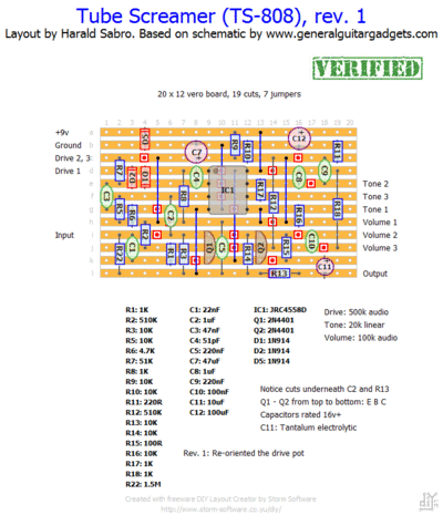
- This is the layout I used to wire up my circuit:
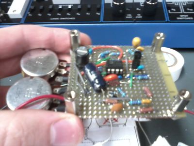
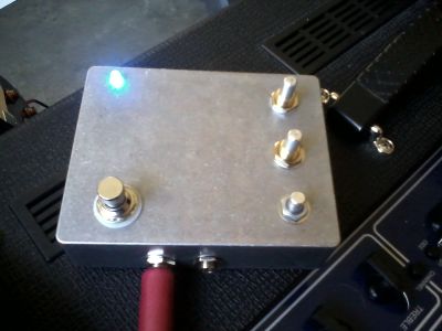
And this is what the circuit looked like when I finished:
Quantitatively:
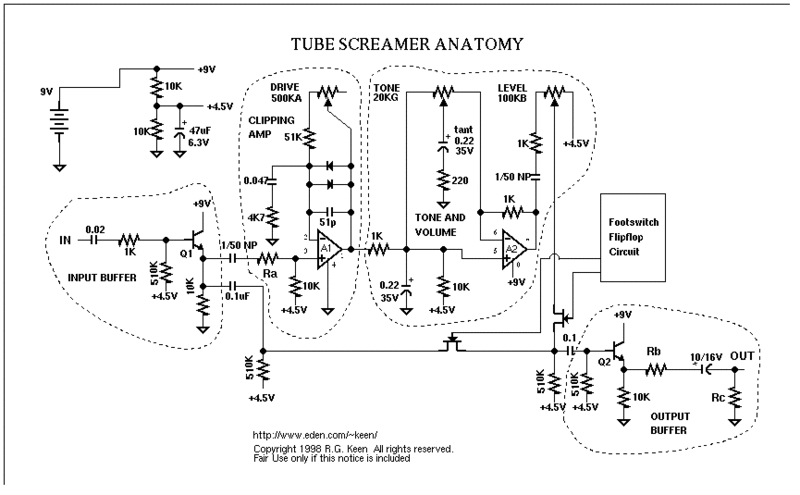
- This is the circuit diagram:
The circuit breaks up into 5 convenient sections: Power Supply (top right), Input Buffer, Clipping Stage, Tone and Volume Stage, and Output Buffer.
The Power supply, Input Buffer, and Output Buffer all serve very basic functions. The Power Supply buffers the DC bias (+9V) and is a voltage divider. The Input Buffer simply adjusts the impedance of the incoming signal to the desirable input impedance, and the Output Buffer does the same for the output impedance.
The most interesting parts of this circuit are the Clipping Stage and the Tone and Volume Stage.
To understand the Clipping Amp, let's start from scratch and build up from there. We start with the Opamp and the resistors. This is a non-inverting opamp with a gain 1+(51k+Pot)/4.7k. So the gain ranges from 12 to about 120. However, when we add the diodes to our circuit, the gain doesn't matter anymore. Under .6 Volts, the diodes do not conduct electricity, but above .6 Volts, the diodes act like a short circuit to the (51k+Pot) effective resistance. This creates a clipped sine wave with a steep slope, and is the basis of diode-clipping distortion effects. Next we add in a couple capacitors to filter the frequency response. the .047uF capacitor in series with the 4.7k resistor creates a high pass filter with a frequency 720Hz. This attenuates lower frequencies out of the Clipping Stage, resulting in a cleaner signal (This is simply a human aesthetic preference). This capacitor also causes a phase shift in the signal, resulting in asymmetrical clipping (another human aesthetic preference). The 51pf capacitor in parallel with the diodes acts as a low pass filter, attenuating higher frequencies and thus softening the clipped edges of the waveform. This makes the distortion seem less harsh.
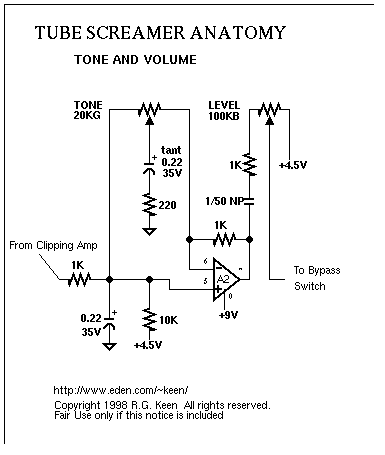
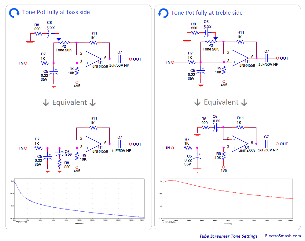
The Volume Stage simply bleeds off some of the output to ground. The Tone Stage is a non-inverting opamp. To understand the Tone Stage, let's look at the Tone Pot turned to both extremes.
When the Tone Potentiometer is all the way to the bass side, The opamp has a gain of 1k/1k=1. The components R7, C5, and C6 create a low pass filter with a cutoff frequency 360Hz, which is low in the hearing range (20-20kHz).
When the Tone Potentiometer is all the way to the treble side, the opamp has a gain of 1+1k/Z(R8+C6), the impedance of R8 and C6. This impedance will be low for high frequencies, and high for low frequencies, resulting in a treble boost. The cutoff frequency for R8 and C6 is 3.25kHz.
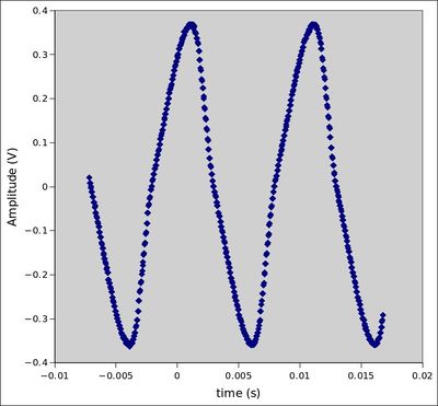
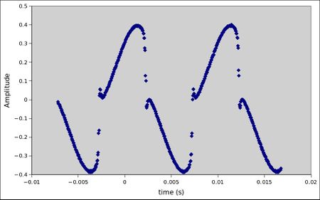
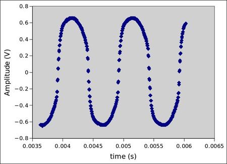
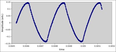
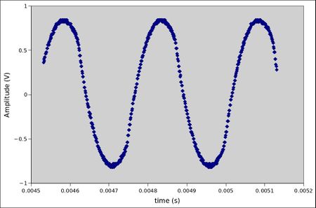
Now that we understand how the circuit works, lets look at the data I took with an oscilloscope. The input is a sine wave, and the voltage is set at 1V peak to peak.
- 100Hz Drive Pot 0%
Drive Pot 100%
Note the y-axis asymmetry of both waveforms. With the drive at 0%, the wave almost resembles a sine wave. The 100Hz waveform is not very heavily clipped when the drive pot is at 100%
- 1kHz Tone Pot 0%
Tone Pot 100%
Note the y-axis asymmetry switches sides between waveforms. With the tone at 0%, the wave resembles a triangle wave. The 1kHz waveform is heavily clipped when the tone pot is at 100%
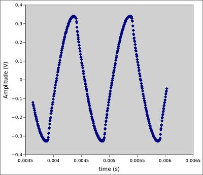
- 4kHz Tone Pot 0%
Tone Pot 100%
With the tone at 0%, the wave resembles a triangle wave. Notice how the peak of the signal at 0% is ~.15v and the peak of signal at 100% is ~1V. The 4kHz waveform is heavily clipped when the tone pot is at 100%, and looks symmetrical on the y-axis.
Trends: Higher frequencies are more heavily clipped, and louder high frequencies have a nearly symmetric waveform. Lower frequencies are less clipped and exhibit more asymmetric behaviour.
Fourier Transform: The output waves were f+2n (n from 0 to infinity), where f is the input frequency and decayed exponentially. This is interesting, because it is not what I would expect to see. I would expect the effect to generate octave harmonics, but octaves are 2*f, not 3*f or 5*f etc. The first harmonic is a fifth (in musical terms) and the second is a major third.

