Difference between revisions of "Lock-in Amplifier"
| Line 14: | Line 14: | ||
== Try it in the Lab == | == Try it in the Lab == | ||
| − | Required Equipment: | + | Required Equipment: Lock-In Amplifier, Function Generator (two outputs), Oscilloscope, BNC Cables |
| − | + | There are multiple lock-in amplifiers in the lab, so the choice of which to use is yours. There is one Model 5104 from Princeton Applied Research that may not be working properly, so you may want to avoid that device. The Model 5202 from Princeton Applied Research was tested and seems to be working as it should. Each lock-in amplifier has slightly different menus/controls, but the basics are all similar. | |
| − | + | Now that we have our equipment and a space in the lab to work we can set up our instruments. Hopefully the function generator that you're using has two outputs, if it doesn't then another function generator might have to be used. One of these outputs will be the reference signal and the other will be the lock-in's input signal. Both signals should be sine waves for now and the frequencies of each can be set to whatever you desire, but if you're using the Model 5202 for example, then there is a corresponding setting on the lock-in for the reference signal frequency. So you should make sure that dial is set to the right setting for whatever reference frequency you're using. For now the reference signal and the input signal | |
| − | |||
| − | |||
| − | |||
| − | |||
Revision as of 15:06, 20 April 2016
Contents
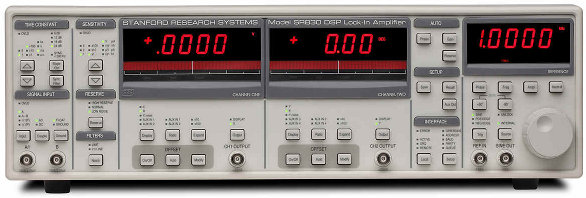
What is a Lock-In Amplifier?
A lock-in amplifier is a type of amplifier used to extract quiet signals out of noisy data. High quality lock-in amplifiers can extract signals up to a million times quieter than the surrounding noise. The output of a lock-in amplifier is a DC signal showing the strength of the signal to be extracted.
How Does a Lock-In Amplifier Work?
Conceptually, a lock-in amplifier works by exploiting the orthogonality of sinusoidal functions. Use of a lock-in amplifier requires a clear reference signal at the frequency of the signal to be extracted. This reference signal is multiplied by the noisy input signal and the product is integrated over a set time. When sinusoidal functions are multiplied together and integrated over a significant amount of time, the result will be zero unless the two sinusoidal functions have the same frequency. This is the before-mentioned orthogonality of sinusoidal functions. For the output of a lock-in, this means that the contributions of all signals not at the reference frequency will be attenuated very close to zero. The output is a DC signal showing the strength of the original input signal at the reference frequency.
From a circuits standpoint, a lock-in amplifier consists of a homodyne detector followed by an adjustable low pass filter. Traditional lock-in amplifiers used analog frequency mixers and RC filters for the demodulation, but modern devices are typically digital and use fast digital signal processing. The out of phase component of the signal that has the same frequency as the reference signal is also attenuated (sine functions are orthogonal to cosine functions of the same frequency), making lock-in amplifiers phase sensitive detectors. Sine and cosine demodulation is usually performed simultaneously (dual phase demodulation).
Try it in the Lab
Required Equipment: Lock-In Amplifier, Function Generator (two outputs), Oscilloscope, BNC Cables
There are multiple lock-in amplifiers in the lab, so the choice of which to use is yours. There is one Model 5104 from Princeton Applied Research that may not be working properly, so you may want to avoid that device. The Model 5202 from Princeton Applied Research was tested and seems to be working as it should. Each lock-in amplifier has slightly different menus/controls, but the basics are all similar.
Now that we have our equipment and a space in the lab to work we can set up our instruments. Hopefully the function generator that you're using has two outputs, if it doesn't then another function generator might have to be used. One of these outputs will be the reference signal and the other will be the lock-in's input signal. Both signals should be sine waves for now and the frequencies of each can be set to whatever you desire, but if you're using the Model 5202 for example, then there is a corresponding setting on the lock-in for the reference signal frequency. So you should make sure that dial is set to the right setting for whatever reference frequency you're using. For now the reference signal and the input signal
