Difference between revisions of "Power Supplies"
Aplstudent (talk | contribs) m |
Aplstudent (talk | contribs) (→General Analog Power Supply Information) |
||
| Line 50: | Line 50: | ||
<li> Slave Output</li> | <li> Slave Output</li> | ||
</ol> | </ol> | ||
| + | |||
| + | The 5V output give out a constant 5V (surprisingly). There are three modes in which the power supply can operate: independent, series and parallel. In independent mode, the master and slave descriptions mean nothing. Only while operating in the series or parallel mode will the master control the slave. In those modes, only the controls for the master will function and it will control both supplies simultaneously. | ||
=== Constant 5V Output === | === Constant 5V Output === | ||
Revision as of 12:27, 5 February 2016
This module will teach you how to use both analog and digital power supplies. While there will be different power supplies in the world in which you will interact, this will gain you the basic knowledge of power supplies to be able to handle any power supply you come across.
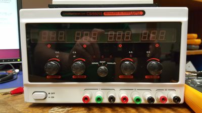
The analog power supply we will work with is the model HY3003D-3 and information can be found in this data sheet or user manual. It is important to note that many different manufacturers will make the HY3003D-3 model of regulated analog power supply. While the interface might be different, the circuit diagram is the same.
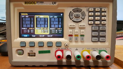
The digital power supply used is the Rigol DP1308A and information can be found here, specifically under the documents tab and looking at either the data sheet or user manual.
For this module, you will need:
- Rigola DP1308A digital DC Power Supply
- HY3003D-3 analog DC Power Supply
- 2 Fluke 179 True RMS multimeters
- An assortment of short wires
- Resistors: 4x100ohm
- A breadboard (or protoboard)
- BNC-Banana Plug Adaptor (with male BNC plug)
- BNC Cables
This module assumes some familiarity with the Multimeters and detail will not always be explained when using these devices.
This module is part of the General Lab Equipment Obstacle Course.
Floating and Grounding
It is important to first discuss the difference between a floating power supply and a grounded power supply.
Ground is a physical connection to the earth (ground). For American three pronged outlets, the extra little third prong will attach to ground.
Floating circuits will have a point of lowest potential, but this value could be anything relative to ground. This is what occurs for American two pronged outlets and batteries. Floating can be used to change voltages when there is already a high voltage occurring. For example boosting 1000V to 1020V, where as a grounded supply would attempt to jump 1000V directly to ground.
Analog Power Supply
This section will cover use of the HY3003D-3 analog DC Power Supply. First discuss the basic nature of the power supply and then discuss the three operating modes.
General Analog Power Supply Information
The HY3003D-3 analog power supply has meaning to its name, breaking into parts HY-30-03-D-3
- HY- Brand/manufacturer
- 30- Maximum output voltage (30 volts)
- 03- Maximum output current (3 Amps)
- D- Display type (LCD)
- 3- Number of outputs (3)
There are three outputs on the analog power supply-
- Floating Constant 5V Output
- Master Output
- Slave Output
The 5V output give out a constant 5V (surprisingly). There are three modes in which the power supply can operate: independent, series and parallel. In independent mode, the master and slave descriptions mean nothing. Only while operating in the series or parallel mode will the master control the slave. In those modes, only the controls for the master will function and it will control both supplies simultaneously.
Constant 5V Output
We will first discuss the constant 5 volt output. First to explore, we use the multimeter in resistance mode to find the internal resistance of the constant power 5V power supply. With the power off, measure the resistance from the positive terminal (red) and the negative terminal (black) of the .
- What resistance do you read across the constant voltage supply? Does this seem reasonable?
This value is important to know, as the internal resistance of the power supply can affect the desired output of the power supply depending on your load circuit. Now measure the resistance between the positive terminal of the constant power supply and ground (a green terminal)
- What resistance do you read? Does this make sense?
The 5V supply by default is a floating supply, so there should be no connection to ground. If we wanted a ground 5 Volt supply, we could connect the negative (black) terminal to the ground (green) with a wire (banana or otherwise).
Operating in Independent Mode
In the center of the panel, you will find the dial/buttons (depending on model) for the operation mode of the analog power supply. For this section, make sure that you are operating in independent mode. In this mode, the two internal power supplies are independent and can be controlled individually.
For each supply, you should be able to identify the current control knob, voltage control knob and three terminals for the voltage (red positive, black negative and green ground).
- What resistance do you read from the positive terminal to the negative terminal of one of the supplies? Does this seem reasonable?
- What resistance do you read from the positive terminal to the negative terminal of the other supply? Are they the same?
- What resistance do you read from the positive terminal to ground? The negative terminal to ground? Does this make sense?
Be default, both supplies are floating. We could connect the negative (black) terminal to the ground (green) with a wire (banana or otherwise) if a grounded power source was required.
- What resistance do you read from the positive terminal of one supply, to the positive terminal of the other supply? Does this make sense?
Even though we are in independent mode, there is still a connection between the two internal supplies. The resistance is very high, so unless the resistance of the circuit load is very high, this should be okay.
- What resistance do you read from the positive terminal of one supply, to the positive terminal of constant 5V supply? Does this make sense?
The 5V supply is not connected in any way to the other two supplies.
We will now move to discuss the different modes the analog power supply can operate in.
Voltage Supply
To explore this, you willset up a very basic circuit to test the power supply. Simply put a voltage across a 100ohm resister as shown. To verify the operation of the power supply, we also want to include a ammeter in the circuit and a voltmeter across the resistor. Either power supply can be used for this section; the controls work the same for both.
With the power off, turn the current control knob all the way clockwise. This will allow for the maximal current to by supplied by the power supply. The voltage control knob should be turned all the way down by turning it all the way counter-clockwise. Turn on the power supply! Adjusting the voltage knob will change the voltage output. The display will show the voltage in Volts. Set the voltage to 7.5V.
- What voltage do you read in the voltmeter? Is it the same as the reading on the power supply?
- What current does the display read?
- What current does the ammeter read? Is it the same as the power supply?
If you turn up the voltage too high, you will burn out the resistor! We can protect delicate circuits with the current control knob. We will be discuss current limiting below.
Replace the 100ohm resistor with the 10kohm resistor and turn the voltage knob to the max.
- What voltage do you read in the voltmeter? Is it the same as the reading on the power supply?
- What current does the display read?
- What current does the ammeter read? Is it the same as the power supply?
In this case, the load can sustain all the current and we max out at the voltage of the power supply. We will now move to discuss the using the power supply as a current source.
... turn off the power supply.
Current Supply
To explore this, we use a slightly different circuit. Put 4 100ohm resisters in parallel then power across the parallel circuit. To verify the operation of the power supply, we also want to include a ammeter in the circuit and a voltmeter across the resistor. Either power supply can be used for this section; the controls work the same for both.
With the power off, turn the voltage control knob all the way clockwise. This will allow for the maximal voltage to by supplied by the power supply. The current control knob should be turned all the way down by turning it all the way counter-clockwise. Turn on the power supply! Adjusting the current knob will change the current output. The display will show the current in Amps. Set the current to 0.3A.
- What current do you read in the voltmeter? Is it the same as the reading on the power supply?
- What voltage does the display read?
- What voltage does the ammeter read? Is it the same as the power supply?
If you turn up the current too high, you will burn out the resistors! When operating in this mode is in important to know the current limit of the load you are using.
Now start adjusting the voltage knob counter clockwise, observing the voltage reading as it goes.
- What happens? Why is this?
This idea is the basics behind the current limiting function of the power supply. The current knob can be set to the desired maximal current and then the voltage can be varied.
Return the current to zero and the voltage to the max. Replace the parallel circuit with a 10kohm resistor.
- What happens if you try to increase the current now? Why is this?
Each individual supply can only give 30V. We will discuss how to get more voltage by operating in the series mode.
...Turn off the power supply
Current Limited Protection Mode
These power supplies can be operated in a current limited mode in order to protect the load from high currents. This section will describe how to set a current limit before the power supply has been connected to the load.
With the supply off and nothing connected to the power supply, turn the current control all the way to the max and the voltage control to the minimum. Turn on the power. At this point we adjust the voltage to the voltage we will be using (or the maximum voltage we will use. At this point set it to 10V. Now connect the positive and negative terminal with a thick banana wire. We can now adjust the current to our desired limit with the current control knob. Set it to 0.3A. Unplug the banana wire and turn the voltage all the way down. Now attach the parallel circuit from the current source section. Start upping the voltage now that the circuit is connected.
- What happens? Why is this?
This is the safest and most effective way to protect a circuit before it is ever connected to the power supply.

