Difference between revisions of "Pound Drever Hall Lock-In"
| Line 21: | Line 21: | ||
==== Current Progress ==== | ==== Current Progress ==== | ||
We started this project this term, so most of our goals have been based off of theory and setting up the Fabry Perot Cavity. Our first goal was to understand the theory behind the PDH method, which is shown in the theory section; this entailed some time doing internet research. This research lead us to some debate on how the feedback circuit works, if you ignore the frequency interaction then the error signal would relax once the cavity was centered and then there would be no feedback to hold the cavity on center; this was shown to be incorrect as we failed to take into account the beat frequency.<br /> | We started this project this term, so most of our goals have been based off of theory and setting up the Fabry Perot Cavity. Our first goal was to understand the theory behind the PDH method, which is shown in the theory section; this entailed some time doing internet research. This research lead us to some debate on how the feedback circuit works, if you ignore the frequency interaction then the error signal would relax once the cavity was centered and then there would be no feedback to hold the cavity on center; this was shown to be incorrect as we failed to take into account the beat frequency.<br /> | ||
| + | <br /> | ||
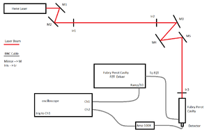
With the theory of this project understood, we moved on to testing the individual components. We started with testing the performance of the grad students Fabry Perot Cavity. The Cavity couldn't be aligned because the rear mirror was misaligned, so there was a limit to how well we could increase the cavity finesse. After much testing the most finesse that could be achieved, that we achieved, was little over 30. Though ideally this would work, the problem id that the misalignment seems to increase largely with the mirror distance meaning that a the finesse changes largely with the cavity length change. The test setup for this measurement is the same test setup as the figure above. | With the theory of this project understood, we moved on to testing the individual components. We started with testing the performance of the grad students Fabry Perot Cavity. The Cavity couldn't be aligned because the rear mirror was misaligned, so there was a limit to how well we could increase the cavity finesse. After much testing the most finesse that could be achieved, that we achieved, was little over 30. Though ideally this would work, the problem id that the misalignment seems to increase largely with the mirror distance meaning that a the finesse changes largely with the cavity length change. The test setup for this measurement is the same test setup as the figure above. | ||
==== Future Plans ==== | ==== Future Plans ==== | ||
Revision as of 16:52, 19 March 2014
Contents
Pound Drever Hall Lock-In Project
Overview
The Pound Drever Hall, or PDH, Lock-In Project is desinged to prepare students for working with tunable lasers, high frequency electronics, and optical Cavities. The objective of this project, as the name entails, is to uses the PHD technique to lock a tunable laser to a cavity. Both the laser and the cavity will be constructed by the students using suplied parts, allowing the students to learn the theory behind tunable lasers and the logistics of constucting an optical cavity.
Theory
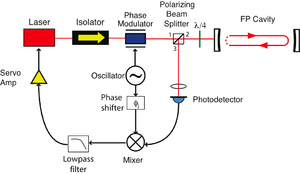
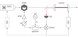
The main concept behind the PHD lock-in method is the use of a Cavity to sense the laser frequency and then adjust the laser based on the laser-cavity frequency difference. The basic way of using a Cavity to measure a lasers frequency is by measuring the transmission or reflection of the cavity at different cavity lengths. Since, the objective is to set the laser to a stabilize a laser around a single frequency, the cavity length will not change. The frequency measurement should also be from the reflected beam of the cavity, so transmitted beam may used. If the cavity resonance is near the laser wavelength, then the reflectance can be approximated by a quadratic function. Though, you can't lock a laser to just the reflected beam because if the laser is slightly off resonance with the cavity there is no way to tell if the laser frequency is higher or lower than the cavity, you can only tell that the laser is off resonance. To fix this note that the derivative of a quadratic function is linear and therefore would fix the frequency ambiguity of the quadratic function. Now, in order to sense the derivative of the reflected beam, with respect to frequency, the laser needs to have is frequency varied. The reason for varying the laser frequency, is to allow for a discrete approximation of a derivative. This means that the reflected beam will have three frequencies, each with there own intensities, based on the reflectance at the respective frequencies. Therefore, when the reflected beam hits the detector, the detector will detect a beat frequency. This beat frequency will create AC signals based on the frequency interaction. In order to know what side of the cavity resonance the laser is on, an analysis of the cavities effect of the lasers side bands is needed. The detector will output quite a few frequencies, but the ones of interest are oscillating at frequency that the laser is being driven at, i.e. the side band beat frequency. to turn these AC signals into a DC signal the use of a mixer is needed, this is to turn the desired ac frequency into (ac)^2. This trick allows the use of the Trig Identity Cos(wt)^2 = 1 + Cos(2wt), meaning that with the addition of a low pass filter, a DC signal based of the magnitude of the the difference of the center frequency and the sideband that gets reflected the most can be obtained.
Our Setup
Our current setup is configured as a Fabry-Perot Interferometer. This setup was used to verify that our Fabry-Perot Cavity was tuned and aligned to the laser. The current setup was to align the Cavity to a specific beam path that another laser could be aligned to. The main reason for having an alignment laser was because our diode laser had a bad mode structure and was low power, by using a Helium-Neon laser we are able to align to Cavity to a high finesse without the difficulty of having to deal with bad modes. Also note that M2 is a flip mirror and the there is another set of beam steering mirrors behind it for the diode laser, which is not shown.
Progress
Past Progress
No past progress as this project just started
Current Progress
We started this project this term, so most of our goals have been based off of theory and setting up the Fabry Perot Cavity. Our first goal was to understand the theory behind the PDH method, which is shown in the theory section; this entailed some time doing internet research. This research lead us to some debate on how the feedback circuit works, if you ignore the frequency interaction then the error signal would relax once the cavity was centered and then there would be no feedback to hold the cavity on center; this was shown to be incorrect as we failed to take into account the beat frequency.
With the theory of this project understood, we moved on to testing the individual components. We started with testing the performance of the grad students Fabry Perot Cavity. The Cavity couldn't be aligned because the rear mirror was misaligned, so there was a limit to how well we could increase the cavity finesse. After much testing the most finesse that could be achieved, that we achieved, was little over 30. Though ideally this would work, the problem id that the misalignment seems to increase largely with the mirror distance meaning that a the finesse changes largely with the cavity length change. The test setup for this measurement is the same test setup as the figure above.


