Difference between revisions of "Mode-locked Erbium-Ytterbium Doped Fiber Laser"
Aplstudent (talk | contribs) |
Aplstudent (talk | contribs) |
||
| Line 41: | Line 41: | ||
[[File:OpticalBench.jpg|500px]] | [[File:OpticalBench.jpg|500px]] | ||
| + | |||
| + | == Data == | ||
Some initial data: pulses occur one per every round trip time (based on length of all fiber elements), measurement of width of pulses is limited by detector resolution. The noise occurring due to imperfect mode interference is often comparable to the main pulses formed but highly unstable. | Some initial data: pulses occur one per every round trip time (based on length of all fiber elements), measurement of width of pulses is limited by detector resolution. The noise occurring due to imperfect mode interference is often comparable to the main pulses formed but highly unstable. | ||
Revision as of 10:13, 17 June 2015
Contents
High Power Pulsed Fiber Lasers
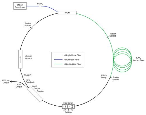
Ring cavity Er-Yb doped fiber laser showing optical bench for Kerr mode locking:
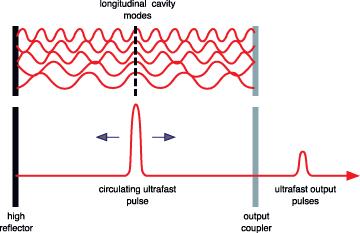
Mode Locking
Mode locking is a technique to create very short periodic pulses by locking modes in phase
Additive-pulse Mode Locking
Nonlinear phase shifts in a single-mode fiber.
Pulses returning from the fiber resonator into the main laser resonator interfere with those pulses which already are in the main resonator.
Constructive interference near the peak of the pulses, but not in the wings, because the latter have acquired different nonlinear phase shifts in the fiber.
Peak of the circulating pulse is enhanced, whereas the wings are attenuated.
The Kerr effect
Nonlinear polarization generated in the medium, which modifies the propagation properties of the light.
The refractive index for the high intensity light beam is modified according to Δn = n' ∙ I (with the nonlinear index n' and the optical intensity I).
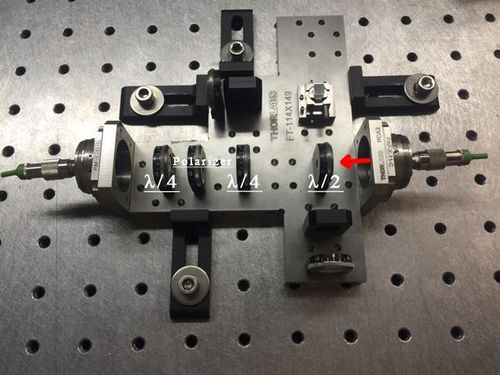
Half wave plate rotates polarization so that the fast axis (highest intensity)is in line with the polarizer;
the signal passes through polarizer with the narrowing of the pulse due to extinguishing of the low-intensity tail-modes;
the quarter wave plate turns linearly polarized light into elliptically polarized light so that the non-linear rotation continues:
Optical bench showing half wave plate, polarizer, and quarter wave plate; another quarter wave plate has been inserted between half wave plate and polarizer to optimize the maximum intensity signal throughput:
Data
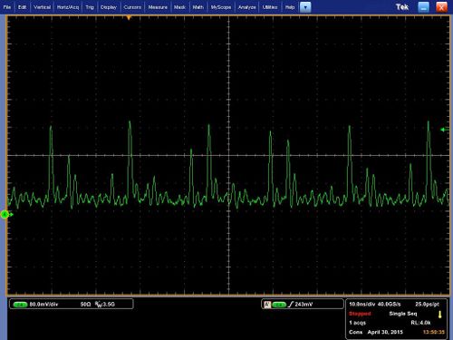
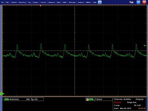
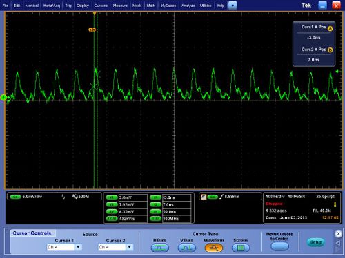
Some initial data: pulses occur one per every round trip time (based on length of all fiber elements), measurement of width of pulses is limited by detector resolution. The noise occurring due to imperfect mode interference is often comparable to the main pulses formed but highly unstable.
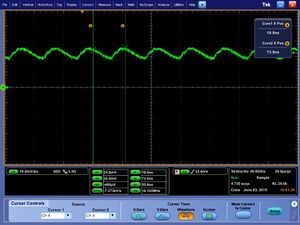
To stabilize the pulses part of the passive fiber was removed and isolator was spliced to the WDM. The pulses became more stable but not as narrow when signal is DC coupled:
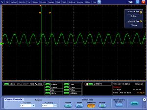
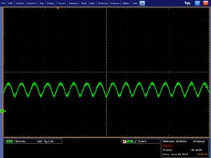
The pulses are seen to be around 10 nanoseconds in width when the signal is AC coupled:
