Difference between revisions of "Master Oscillator Power Amplifier Pulsed Laser"
Aplstudent (talk | contribs) |
Aplstudent (talk | contribs) |
||
| Line 1: | Line 1: | ||
'''MOPA (Master Oscillator Power Amplifier)''' | '''MOPA (Master Oscillator Power Amplifier)''' | ||
| − | This fiber laser | + | The master oscillator produces a highly coherent beam, and an optical amplifier is used to increase the power of the beam while preserving its main properties. The master oscillator has no need to be powerful, and has no need to operate at high efficiency because the efficiency is determined mainly by the power amplifier. |
| + | |||
| + | With a MOPA instead of a laser, it can be easier to reach the required performance e.g. in terms of linewidth, wavelength tuning range, beam quality or pulse duration if the required power is very high. This is because various performance aspects are decoupled from the generation of high powers. This gives extra flexibility, e.g. when a gain-switched laser diode is used as a seed laser. | ||
| + | |||
| + | The same aspects apply to other kinds of modulation, e.g. intensity or phase modulation: it may be advantageous to modulate the low-power seed laser, or to use an optical modulator between seed laser and power amplifier, rather than to modulate a high-power device directly. Slower power modulation may be done by adjusting the amplifier's pump power, without significantly affecting e.g. the obtained pulse duration or wavelength. | ||
| + | |||
| + | The combination of an existing laser with an existing amplifier (or an amplifier chain) may be simpler than developing a new laser with higher output power. | ||
| + | |||
| + | The optical intensities are lower in an amplifier, compared with the intracavity intensities in a laser. | ||
| + | |||
| + | However, the MOPA approach can also have disadvantages: | ||
| + | |||
| + | The resulting laser noise tends to be higher, since an amplified source can not reach the shot noise level (→ amplifier noise). Effects of drifts of the seed power may be suppressed, however, if the amplifier is operated in a strongly saturated regime. | ||
| + | |||
| + | A MOPA can be sensitive to back-reflections, which are amplified again before entering the master laser. This feedback sensitivity can often be cured only by placing a Faraday isolator behind the amplifier. Particularly for high-power pulsed devices, this can introduce serious limitations. | ||
| + | |||
| + | '''Stages of the fiber laser:''' | ||
1st: Master Oscillator (this is the stage that will contain the graphene and will produce the pulsing) | 1st: Master Oscillator (this is the stage that will contain the graphene and will produce the pulsing) | ||
Revision as of 14:50, 16 June 2015
MOPA (Master Oscillator Power Amplifier)
The master oscillator produces a highly coherent beam, and an optical amplifier is used to increase the power of the beam while preserving its main properties. The master oscillator has no need to be powerful, and has no need to operate at high efficiency because the efficiency is determined mainly by the power amplifier.
With a MOPA instead of a laser, it can be easier to reach the required performance e.g. in terms of linewidth, wavelength tuning range, beam quality or pulse duration if the required power is very high. This is because various performance aspects are decoupled from the generation of high powers. This gives extra flexibility, e.g. when a gain-switched laser diode is used as a seed laser.
The same aspects apply to other kinds of modulation, e.g. intensity or phase modulation: it may be advantageous to modulate the low-power seed laser, or to use an optical modulator between seed laser and power amplifier, rather than to modulate a high-power device directly. Slower power modulation may be done by adjusting the amplifier's pump power, without significantly affecting e.g. the obtained pulse duration or wavelength.
The combination of an existing laser with an existing amplifier (or an amplifier chain) may be simpler than developing a new laser with higher output power.
The optical intensities are lower in an amplifier, compared with the intracavity intensities in a laser.
However, the MOPA approach can also have disadvantages:
The resulting laser noise tends to be higher, since an amplified source can not reach the shot noise level (→ amplifier noise). Effects of drifts of the seed power may be suppressed, however, if the amplifier is operated in a strongly saturated regime.
A MOPA can be sensitive to back-reflections, which are amplified again before entering the master laser. This feedback sensitivity can often be cured only by placing a Faraday isolator behind the amplifier. Particularly for high-power pulsed devices, this can introduce serious limitations.
Stages of the fiber laser:
1st: Master Oscillator (this is the stage that will contain the graphene and will produce the pulsing)
2nd: Single-Mode Power Amplifier
3rd: Double-Clad Power Amplifier
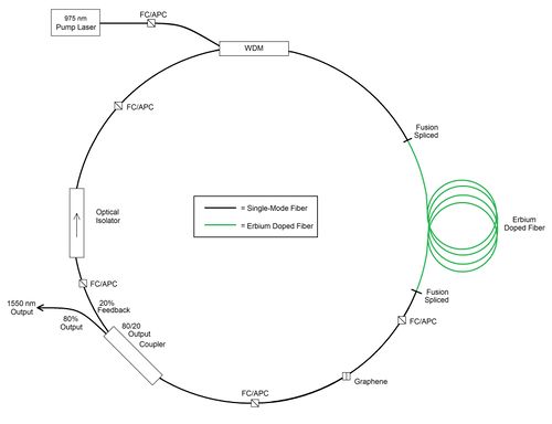
Master Oscillator with graphene as saturable absorber:
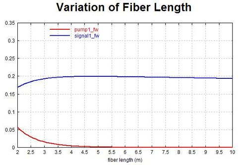
The lengths of Erbium-doped fiber are chosen based on RP Fiber Power simulation:
Application of Graphene to the Tip of a Fiber Connector
We want to use graphene as a saturable absorber for our MOPA
In order to do that, we need to get graphene onto the tip of a fiber connector:
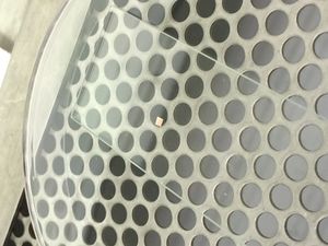
Cut Out a Small Square From the Graphene Sample
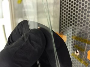
To cut the graphene sample, use an exacto blade and press firmly onto the foil, no sawing motion
Once the small square is free, place it onto a glass slide and with another glass slide cover it
Press the two slides together to flatten the foil so that hopefully the suction in the next step will be strong enough to hold it in place
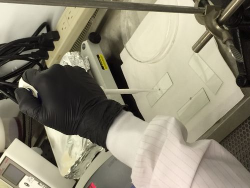
Put a Droplet of Isopropyl Alcohol onto the Copper Square
Careful not to wet the copper square, a bead is needed in order to adhere to the target substrate
Once there is a bead of Isopropyl on the copper square, lower the fiber connector slowly down to it. We used a translation stage to lower the fiber connector down slowly and smoothly
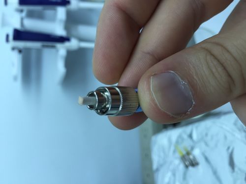
When the tip of the fiber connector breaches the top of the bead, the copper square should be sucked upward and flatten on the surface of the fiber connector tip:
Bake the Fiber Connector on a Hot Plate
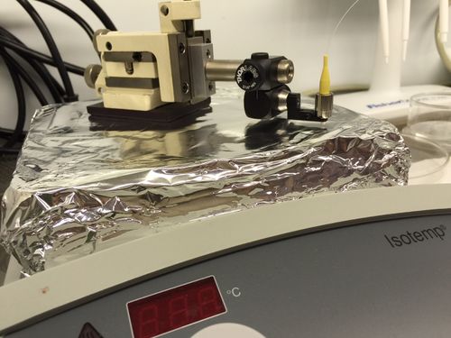
Place the whole translation stage onto a hot plate set to 120C
Lower the translation stage so that the tip of the fiber connector is right above the hotplate
Let it bake for an hour and a half:
Etch the Copper Substrate
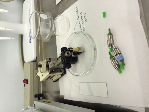
Fill a glass petri dish with copper etchant (we used sodium persulphate)
Lower the fiber connector tip into the copper etchant slowly
Let it sit for an hour, and then dip the fiber connector into DI water the same way to remove excess etchant:
